INTRODUCTION1 - 3
D-MAXE with OI-B/OI-N www.maxcessintl.comMI 2-296 1 D
Operating principle The D-MAXE system consists of various modules that can be
combined depending on the specific application.
Modules D-MAXE Controllers
– integrated into a guiding system or for wall mounting
–D-MAXE 1 Controller:
for the drive of a control loop
–D-MAXE 2 Controller:
For the drive of two independent control loops
or
one control loop with automatic sensor positioning
–D-MAXE 3 Controller:
For the drive of three independent control loops or
combinations of control loops with automatic sensor
positioners
D-MAX Operator interfaces
– Operator interface for desk installation or wall mounting
– Operator interface OI-B: basic version for operating
D-MAXE Controllers
– Operator interface OI-N: network version
Depending on operating equipment, from one to four
D-MAXE Controllers and one additional network device
Option:
a CompactCom interface (fieldbus) for communication
with
Programmable Logic Controllers (PLCs)
– PC-based virtual operator interface
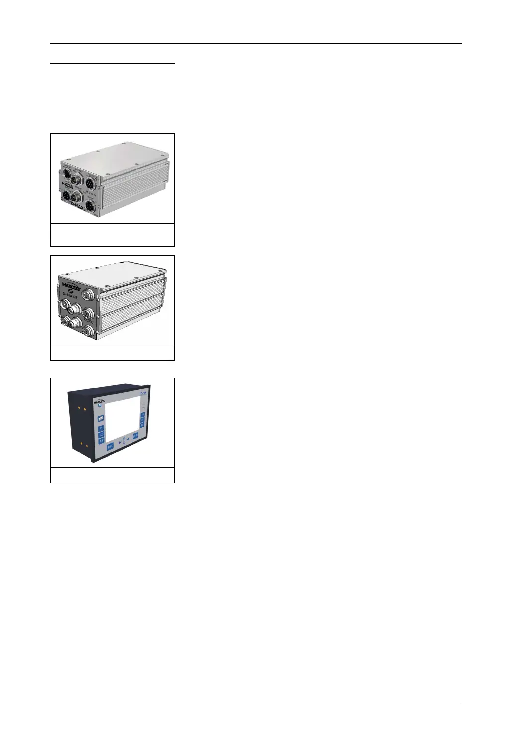
Figure 1.1: Controller, D-MAXE 1
and D-MAXE 2
Figure 1.2: Controller, D-MAXE 3
Figure 1.3: Operator interface