INTRODUCTION 1 - 4
D-MAXE with OI-B/OI-Nwww.maxcessintl.com MI 2-296 1 D
Einführung.fm
Operating principle
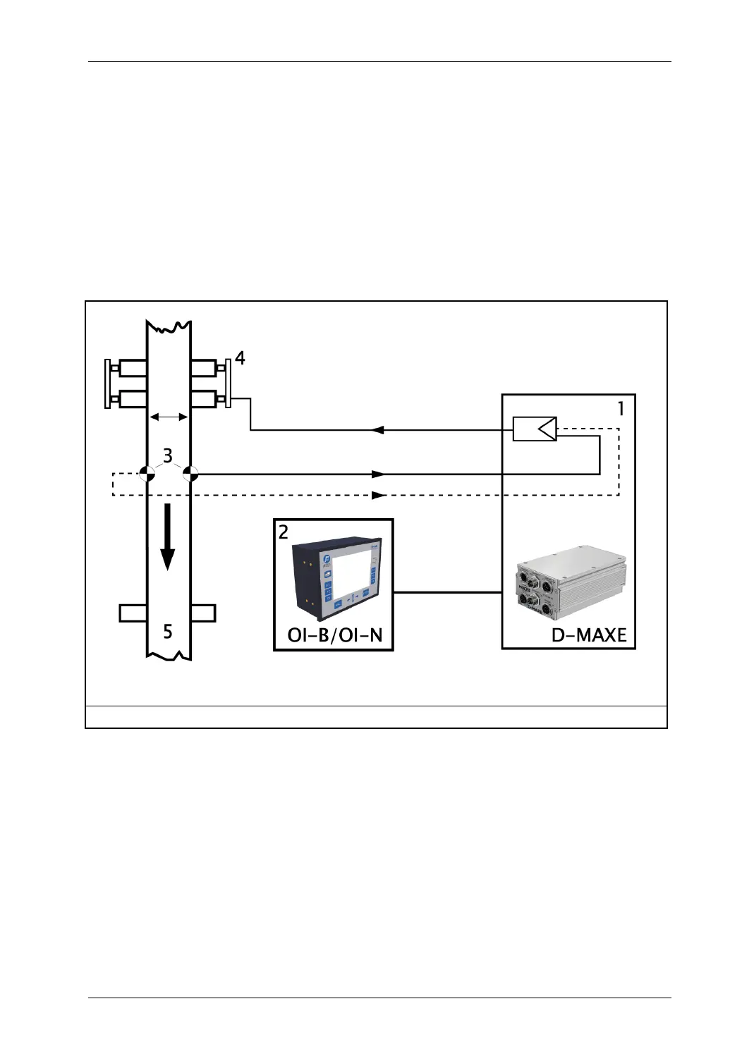
Figure 1.4
shows an example of edge guiding (optionally center
guiding) with a D-MAXE system.The D-MAXE system consists of
a D-MAXE 1 Controller (1) and an operator interface OI-B (2).
A sensor (3) senses the web edge of a material web and
determines the current position of the web. The D-MAXE 1
Controller receives this information and guides the material web
(5) by means of an actuator (4) so that it is always in the desired
target position.
1 D-MAXE 1 Controller
2 Operator interface OI-B/OI-N
3 Sensor(s)
4 Actuator (offset pivot guide)
5 Material web
--- optional
Figure 1.4: Operating principle of a control loop with modules of the D-MAXE system