Chapter 3 Front panel operation
38
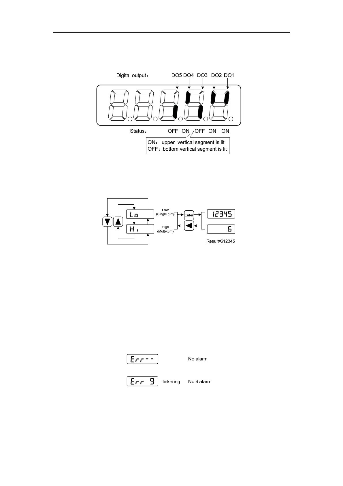
6. Output terminal DO [note 6]
A vertical segment of LED shows an output status. The lit top vertical segment shows the
DO output to be “ON” and the lit bottom vertical segment to be “OFF”.
7. Rotor absolute position [note7]
The rotor absolute value position is represented by the combination of low and high
position, which are selected from the menu.
Single turn represents the position of the rotor relative to the stator in a revolution, and
turns one into a period. The unified pulse unit takes the encoder Z pulse as the origin. The
range is 0 to 65535, and the value is 0 when the Z pulse appears.
Multiple turns indicate the number of rotor turns, the range of which is 0 ~ 65535.
8. Alarm code [note 8]
The "Err" followed by two minus symbols indicates no alarm and by digital number
indicates an error code number that is flickering. When alarm appears, the error code number
displays automatically on the front panel LED. During the error status, the monitor mode can
be changed to other mode by pressing buttons, but the decimal point of the last LED is still
flickering and shows existence of an alarm.