Chapter 5 Parameters
86
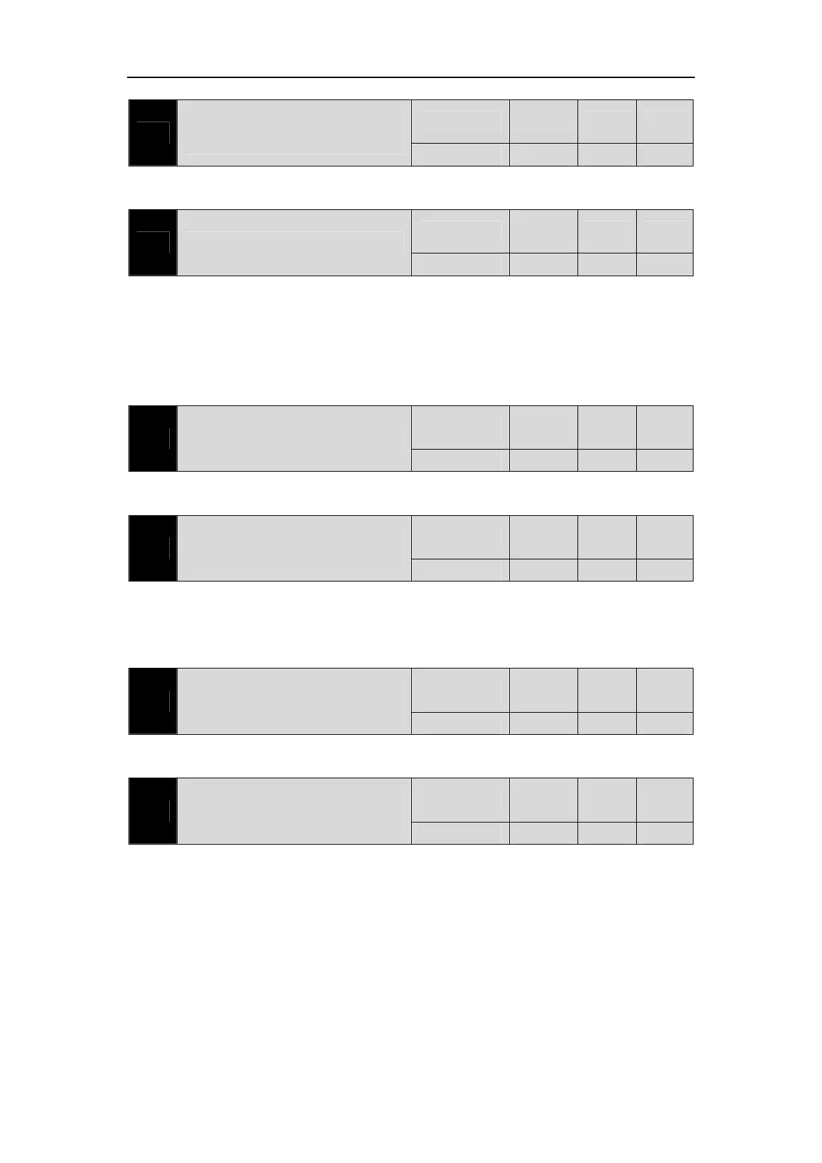
P229
Intermediate frequency vibration
suppression switch
Range
Default
value
Unit Usage
0~2 0 P
Parameter meaning:
0: Invalid 1: Manual setting 2: Automatic setting
P270 Model tracking control switch
Range
Default
value
Unit Usage
0~3 0 P
It is suggested that Fn1 function should be used to deduce the load inertia first.
Suitable for position control, select appropriate parameters according to different loads,
can improve the response of the system.
Parameter meaning:
0: Model tracking is invalid 1: Applicable to rigid load
2: Suitable for flexible load 3: General purpose
P271 Model tracking control gain
Range
Default
value
Unit Usage
10~2000 40 Hz P
Model tracking control gain, modes 1 ~ 3 are valid.
The higher the value, the faster the response, too much may bring noise.
P273
Model tracking positive direction
proportional control
Range
Default
value
Unit Usage
0~1000 100 % P
Model to trace the positive direction control deviation, mode 1 ~ 3 are valid.
By adjusting this parameter, the forward and reverse response speed can be adjusted
separately.
The larger the value is, the greater the feedforward effect of the torque ring will be.
P274
Model tracking reverse proportional
control
Range
Default
value
Unit Usage
0~1000 100 % P
Instructions are the same as P273.
P277
Model tracking velocity
compensation feedforward
Range
Default
value
Unit Usage
0~1000 100 % P
Model to trace the speed feedforward compensation, the value, the greater the speed loop
feedforward action, the greater the too much may lead to noise.
Modes 1 to 3 are valid.