3-7
1. Open the control panel. (See page 3-2)
2. Lean the control panel down, leaving it on
the lower hooks, to access the automatic
door release module.
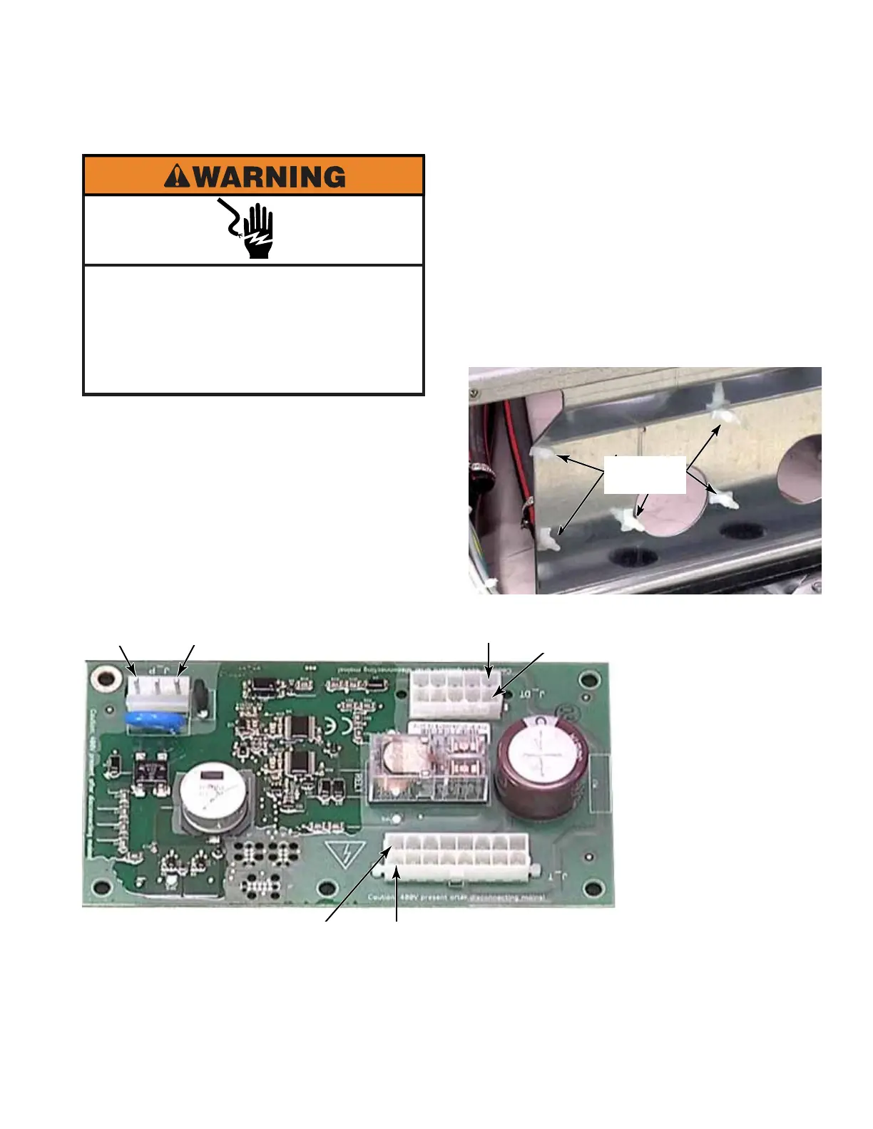
3. Disconnect wire connectors from board.
Press thumb lock and pull connector off.
4. To remove the board from the control panel,
squeeze the five standoffs, with needle
nose pliers, to release corners of the board.
5. Pull the board away from the washer and
remove it.
6. If replacing the chemical dispenser support,
remove the five standoffs that secure the
automatic door release module. Reinstall
them in the new support.
Electrical Shock Hazard
Disconnect power before servicing.
Failure to do so can result in death or
electrical shock.
Replace all parts and panels before
operating.
AUTOMATIC DOOR RELEASE MODULE - PD MODELS
Five
Standoffs
L1
Brown
L2
Grey
DT1
DT6
T1 T6
DT1 - Brown - To L1
DT4 - White - To DL16
DT5 - Black - To DL8
DT6 - Orange - To DL2
DT8 - Purple - To DL13
(L2 - 230VAC)
T2 - Orange - To Door Lock #4 - Closed Switch
T9 - Brown - To Door Lock #8 - Closed Switch
T10 - Red - To Door Lock #7 - Locked Switch
T13 - Purple - To Door Lock #3 - Locked Switch
T16 - White - To Door Lock #6 - Solenoid Coil
 Loading...