4 - 6 VM600 MPS hardware manual (standard version) MAMPS-HW/E
Edition 17 - February 2018
Overview of MPC4 operation
MPC4 / IOC4T CARD PAIR
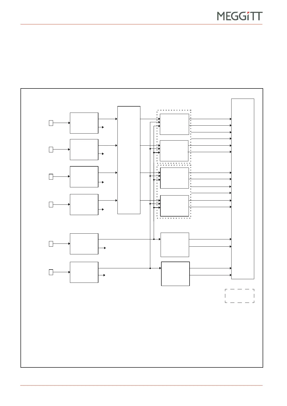
4.3 Overview of MPC4 operation
The MPC4 card implements a variety of signal processing and monitoring functions, each of
which requires real-time continuous processing of the inputs. It can execute up to a maximum
of four processes simultaneously, either on one sensor or on a combination of up to four
sensors.
The block diagram in Figure 4-3 summarises the operation of the MPC4 card.
Figure 4-3: Operation of MPC4 machinery protection card
Meas.
Sensor 1
Meas.
Sensor 2
Meas.
Sensor 3
Meas.
Sensor 4
Speed
Sensor 1
Speed
Sensor 2
Sensor signal
conditioning
Sensor signal
conditioning
Sensor signal
conditioning
Sensor signal
conditioning
Speed
sensor
signal
Speed
sensor
signal
Raw
*
signal
Raw *
signal
Raw
*
signal
Raw *
signal
“Raw” speed signal
(TTL compatible)
“Raw” speed signal
(TTL compatible)
Signal routing
Signal
processing /
monitoring
Signal
processing /
monitoring
Signal
processing /
monitoring
Signal
processing /
monitoring
Speed meas.
and monitoring
Dual-channel
processing
VME
RS-232
IOC
Alarms / OK
Processed values
**
Alarms / OK
Processed values
**
Alarms
Processed values
**
Alarms / OK
Processed values
**
Alarms / OK
Processed values
**
Alarms
Processed values
**
Speed value**
OK
Speed value
**
OK
Notes
*The raw measurement signals and TTL-conditioned speed signals are output on the
MPC4 card’s panel BNC connectors and are also sent to the IOC4T.
**The “processed values” include the two “monitored” values. They also include the OK
levels of the sensors. The “speed values” are also monitored and include the OK value of
the sensor.
Speed meas.
and monitoring
 Loading...


