VM600 MPS hardware manual (standard version) MAMPS-HW/E 7 - 31
Edition 17 - February 2018
Narrow-band fixed frequency
PROCESSING MODES AND APPLICATIONS
7.18Narrow-band fixed frequency
1) Description
Narrow-band fixed frequency tracking (NBFS) processing is similar to narrow-band (tracking)
vibration (NB) processing in that it uses a narrow-band filter with a high Q-factor (Q=28) in
order to allow specific machine vibrations to be isolated. However, this technique uses a fixed
frequency narrow-band filter that is defined in terms of a particular shaft speed (so it does not
track the machine speed).
(2) Block diagram
Principal features:
• Calculation of amplitude only (no 1/REV input)
• Fixed-frequency narrow-band filter with a high Q-factor (Q = 28)
Note: The Q-factor of 28 is a fixed value (hard-coded constant)
• Acceleration output (g, m/s
2
or inch/s
2
)
• Velocity value processing (g, m/s
2
or inch/s
2
converted to mm/s or inch/s).
The frequency of interest is defined in terms of a fixed machine speed (Center Speed
in RPM), as follows:
Centre frequency, f
0
= Center Speed in RPM / 60
Bandwidth, BW = f
0
/ Q , where Q = 28
The centre frequency f
0
is the geometric mean of the bandwidth, defined by the 3 dB cutoff
frequencies: lower cut-off frequency (f
1
) and upper cut-off frequency (f
2
).
Bandwidth, BW = f
0
/ Q = f
2
− f
1
, where Q = 28
Which allows the cutoff frequencies be calculated using:
Lower cut-off frequency, f
1
=f
0
((1+(1/4Q
2
))
0.5
− (1 / 2Q) ) , where Q = 28
Upper cut-off frequency, f
2
=f
0
((1+(1/4Q
2
))
0.5
+ (1 / 2Q) ) , where Q = 28
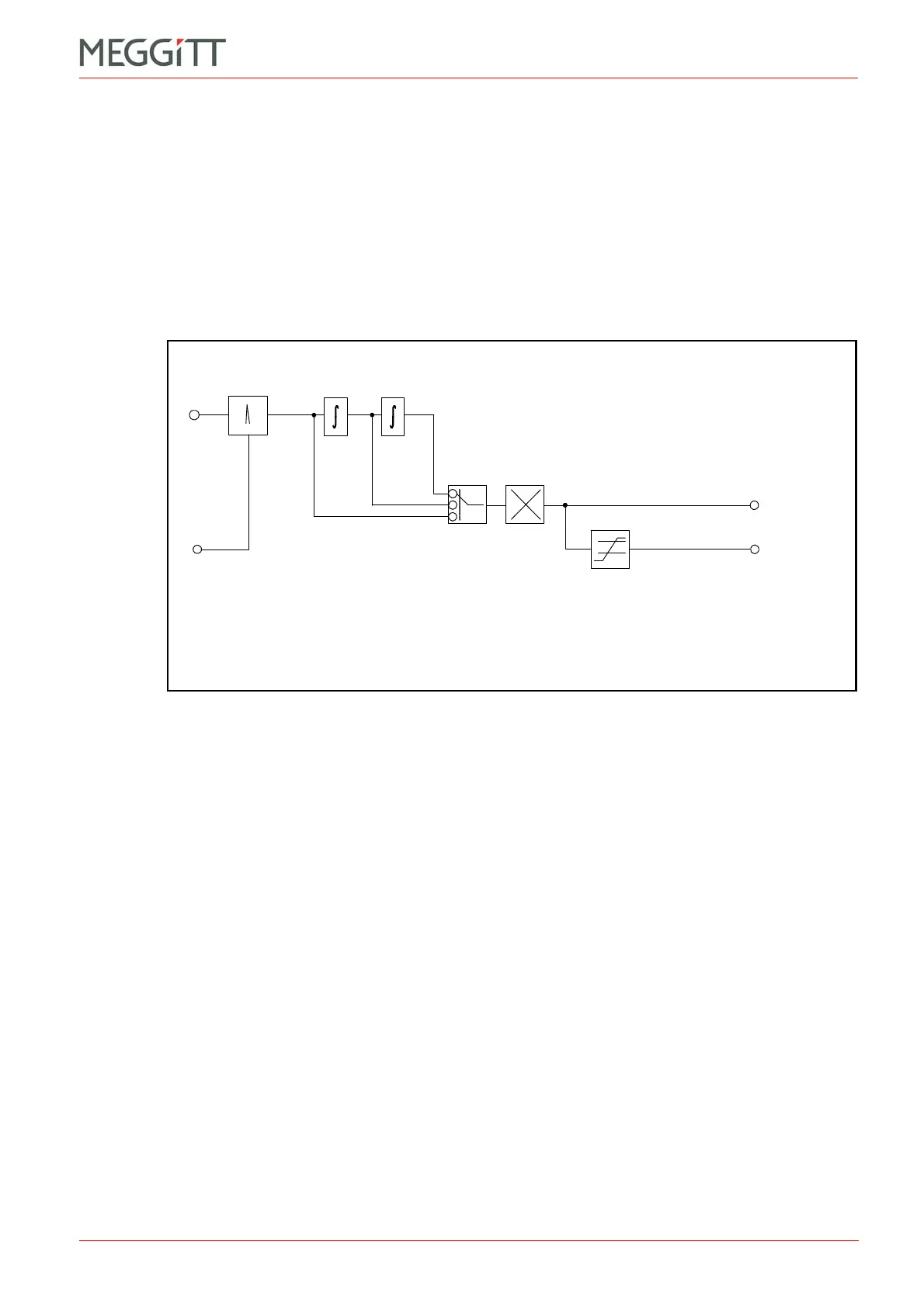
Vib.
input
Narrow band
Output 1
amplitude
value
Scaling:
RMS
Mean
Peak
Peak-Peak
Alarm level
detector
Output 1
amplitude
alarm
Speed in RPM
(fixed)
Ampl.
Figure 7-29: Block diagram showing narrow-band fixed frequency processing
 Loading...


