9 - 8 VM600 MPS hardware manual (standard version) MAMPS-HW/E
Edition 17 - February 2018
Connecting vibration and pressure sensors
CONFIGURATION OF MPC4 / IOC4T CARDS
9.2.1 General considerations
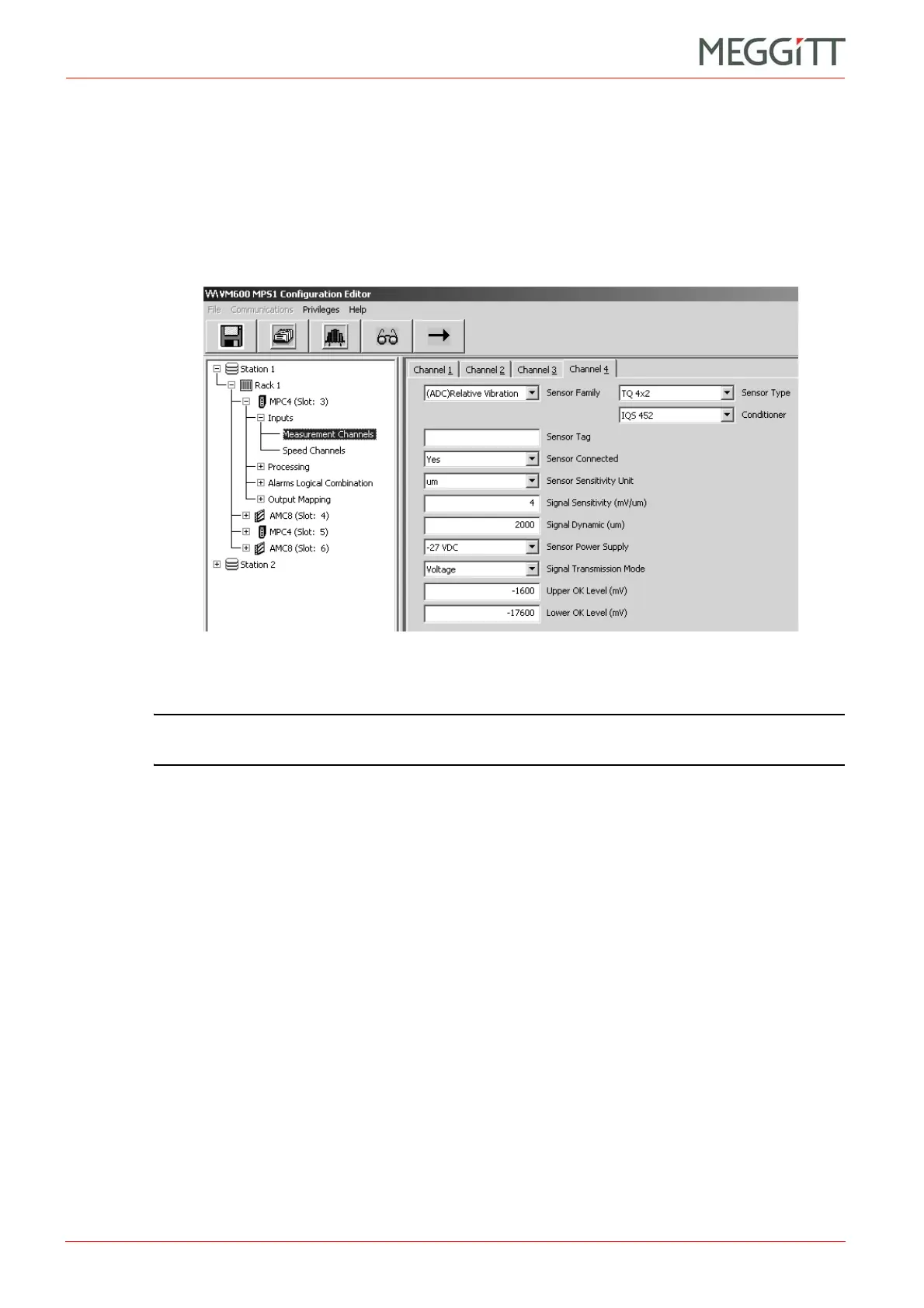
The IOC4T circuitry associated with the PS, HI, LO and SHIELD terminals (see Figure 9-3)
is configurable using the VM600 MPS software. More specifically, the fields in the property
sheets for the Measurement Channels node (a child of the Inputs node) in the tree structure
(left) are used to configure switches Sw1 and Sw2 automatically and appropriately for a
variety of applications and different types of transducer and/or signal conditioner (see
Figure 9-2).
NOTE: Refer to the relevant manual for further information: VM600 MPS1 software
manual or VM600 MPS2 software manual.
Switch Sw1 is set according to whether a voltage-modulated or a current-modulated signal is
provided by the transducer or transducer and signal conditioner system:
• Voltage-modulated signal: Sw1 open.
• Current-modulated signal: Sw1 closed.
The position of Sw1 is determined by the setting of the Signal Transmission Mode field (see
Figure 9-2). The correct setting (current or voltage) is chosen automatically by the program
when standard transducers and signal conditioners from Meggitt Sensing Systems’
Vibro-Meter product line are selected (using the Sensor Type and Conditioner fields). For
non-Vibro-Meter devices, the operator must enter the appropriate setting (current or voltage)
in the Signal Transmission Mode field.
Switch Sw2 is used to connect the IOC4T card's sensor power supply to either the PS or the
HI terminal.
The position of Sw2 is determined by the setting of the Sensor Power Supply field (see
Figure 9-2). The correct setting is chosen automatically when standard transducers and
signal conditioners from Meggitt Sensing Systems’ Vibro-Meter product line are selected
(using the Sensor Type and Conditioner fields). For non-Vibro-Meter devices, the operator
must enter the appropriate setting in the Sensor Power Supply field. The option No Supply
sets Sw2 to position 2. Any other option (+27 VDC, −27 VDC, +15 VDC or +6.16 mA) sets
Sw2 to position 1.
Figure 9-2: The Inputs (parent) and Measurement Channels (child) nodes
in the MPS1 software
 Loading...


