VM600 MPS hardware manual (standard version) MAMPS-HW/E 10 - 5
Edition 17 - February 2018
Connecting sensors to the IOC8T
CONFIGURATION OF AMC8 / IOC8T CARDS
10.2Connecting sensors to the IOC8T
The IOC8T panel has six terminals for each of the 8 measurement channels. These terminals
are as follows:
• I Current source output
• H Positive signal input
• R Measuring resistor input for current-based signals (4 to 20 mA)
• C Common input
• S Shield
• (Unnamed) A terminal for chassis ground.
Typical connection diagrams are shown below.
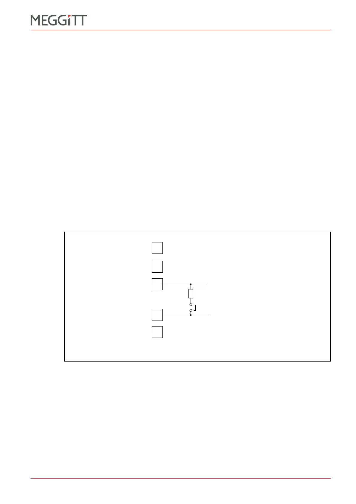
10.2.1 Setting of jumper J805
A measuring resistor (Rm) for current-based signals can be switched in across terminals R
and C by jumper J805. The setting of this jumper is not important for most connection cases,
apart from the following exceptions:
• The jumper must be removed for 4-wire RTD connection using the “true 4-wire
arrangement”. See Figure 10-7 (b).
• The jumper must be placed for measuring current-based signals. See Figure 10-8.
Each channel has its own jumper J805. These are identified by a suffix (A to H) as follows:
Channel 1: Jumper J805_A Channel 5: Jumper J805_E
Channel 2: Jumper J805_B Channel 6: Jumper J805_F
Channel 3: Jumper J805_C Channel 7: Jumper J805_G
Channel 4: Jumper J805_D Channel 8: Jumper J805_H.
The position of these jumpers on the IOC8T is shown in Figure 10-3.
Figure 10-2: Measuring resistor and jumper J805
R
m
Measuring resistor (50 )
Jumper J805
 Loading...


