VM600 MPS hardware manual (standard version) MAMPS-HW/E 13 - 7
Edition 17 - February 2018
Configuring RS-485 terminations for RS, A and B serial communications
CONFIGURATION OF CPUM / IOCN CARDS
13.4Configuring RS-485 terminations for RS, A and B serial communications
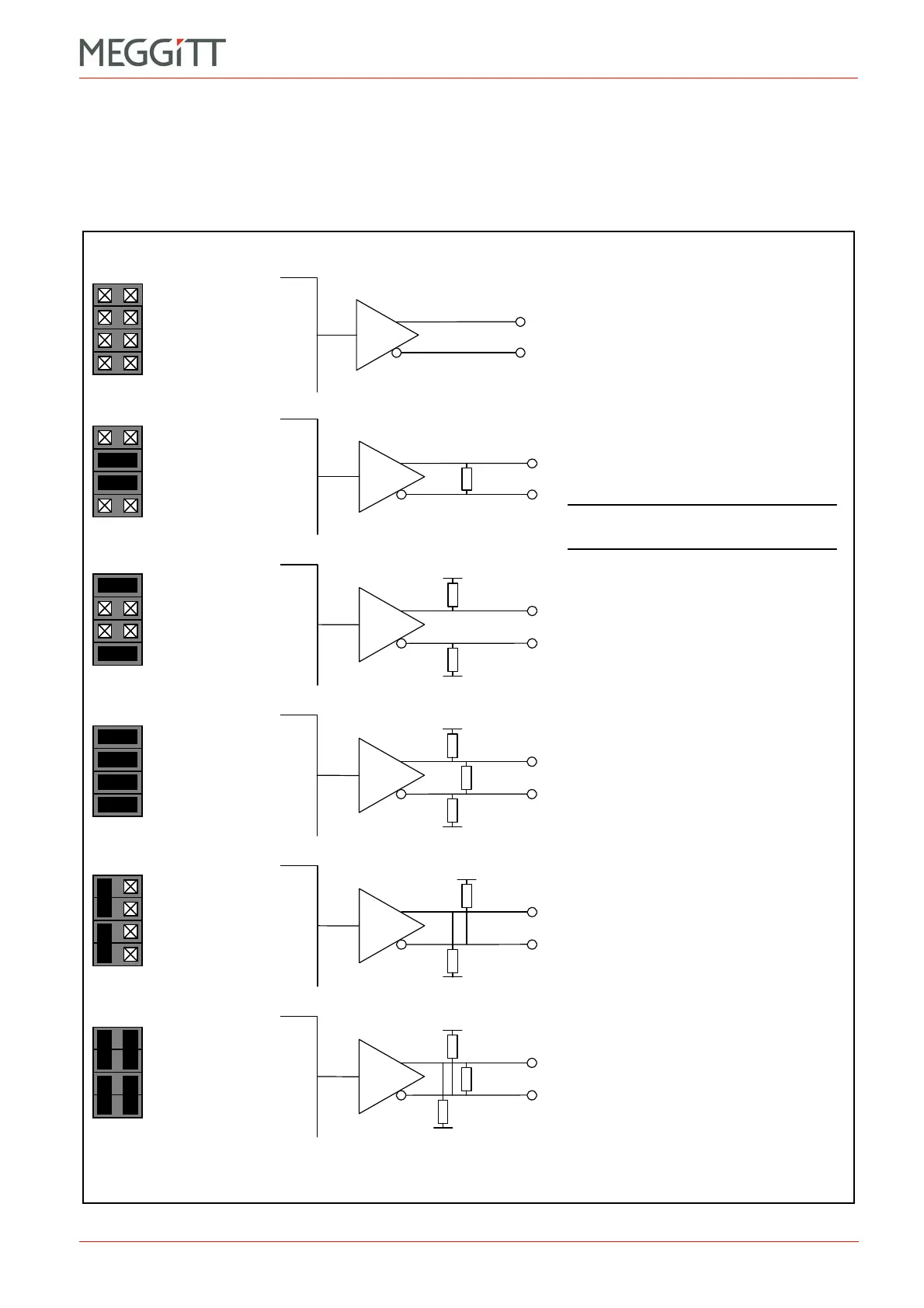
For RS serial communications (RS-485 only), and A and B serial communications, jumpers
on the CPUM card are used to configure terminations.
Each RS-485 differential pair can be terminated in one of six ways, as shown in Figure 13-9.
Figure 13-9: CPUM card jumper settings for various types of RS-485 terminations
J31 (J35)
J32 (J36)
J33 (J37)
J34 (J38)
J31 (J35)
J32 (J36)
J33 (J37)
J34 (J38)
J31 (J35)
J32 (J36)
J33 (J37)
J34 (J38)
J31 (J35)
J32 (J36)
J33 (J37)
J34 (J38)
J31 (J35)
J32 (J36)
J33 (J37)
J34 (J38)
J31 (J35)
J32 (J36)
J33 (J37)
J34 (J38)
(a) Not terminated
Line driver connects directly to the
differential pair.
(b) Terminated
Differential pair is terminated with 120
resistance between the signal lines.
(c) Pulled inactive
Differential pair is pulled apart to mimic no
character being transmitted from UART.
(d) Pulled inactive and terminated
Differential pair is terminated with 120 Ω and
is pulled apart to mimic no character being
transmitted.
(e) Pulled active
Differential pair is pulled apart to mimic
UART sending a break condition.
(f) Pulled active and terminated
Differential pair is terminated with 120 Ω and
is pulled apart to mimic a break condition.
UART
pin
UART
pin
UART
pin
UART
pin
UART
pin
UART
pin
NOTE: This is the default factory
setting.
LK13 to
LK16
A
B
C
D
LK13 to
LK16
A
B
C
D
LK13 to
LK16
A
B
C
D
LK13 to
LK16
A
B
C
D
LK13 to
LK16
A
B
C
D
LK13 to
LK16
A
B
C
D

 Loading...


