VM600 MPS hardware manual (standard version) MAMPS-HW/E 13 - 9
Edition 17 - February 2018
Additional jumpers on the IOCN card
CONFIGURATION OF CPUM / IOCN CARDS
13.5Additional jumpers on the IOCN card
13.5.1 Linking the RS and A serial communications connectors
On the IOCN card, the RS connector used for secondary serial communications (RS-232 or
RS-485) can be linked pin-by-pin to the two group A connectors.
NOTE: Linking the RS and A serial communications connectors requires that the optional
serial communications module (AIM104-COM4 or equivalent) is not fitted to the
CPUM card so that two group A connectors are available.
Linking the RS and A serial communications connectors in this way is the only way
that RS-232 signals can be used with the group A connectors.
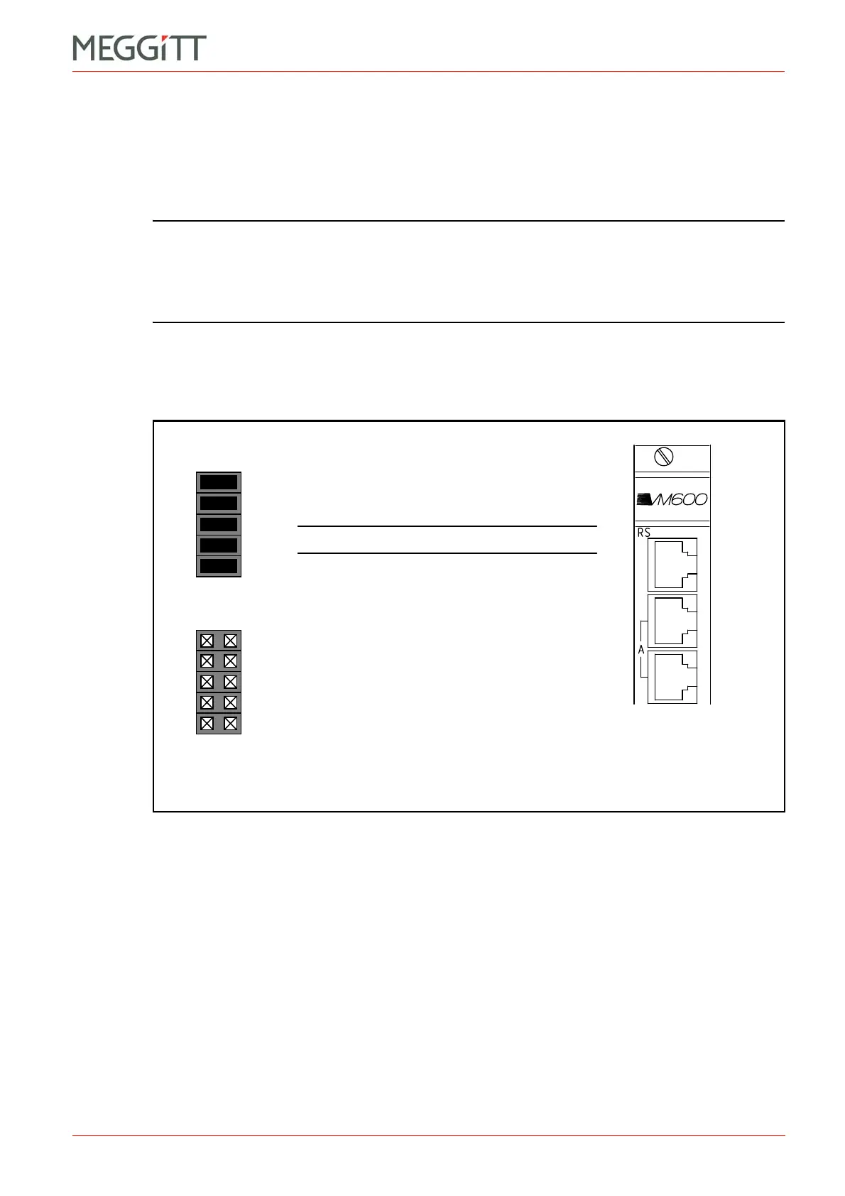
The RS and A serial communications connectors are linked using jumpers J20 to J24 on the
IOCN card, as shown in Figure 13-10.
The location of the jumpers on the IOCN card can be found using Figure 13-15.
(a) RS connector linked to the two A connectors
(b) Independent RS and A connectors
Part of IOCN panel showing
the RS and A connectors
J20
J21
J22
J23
J24
J20
J21
J22
J23
J24
Figure 13-10: IOCN card jumpers to link the RS and A connectors
NOTE: This is the default factory setting.

 Loading...


