11 - 4 VM600 MPS hardware manual (standard version) MAMPS-HW/E
Edition 17 - February 2018
Connecting the RLC16 relays
USING THE RLC16 CARD
11.2Connecting the RLC16 relays
The RLC16 panel has three screw terminals for each of its 16 relays. These terminals are as
follows:
• NC – The normally closed relay contact
• NO – The normally open relay contact
• COM – The common relay contact.
The actual behaviour of each individual relay depends on the jumpers on the RLC16 card.
For example, a relay can be configured to be normally energised (NE) or normally
de-energised (NDE).
11.2.1 Relay terminology
See 9.4.1 Relay terminology.
11.2.2 Operation of relays
See 9.4.2 Operation of relays.
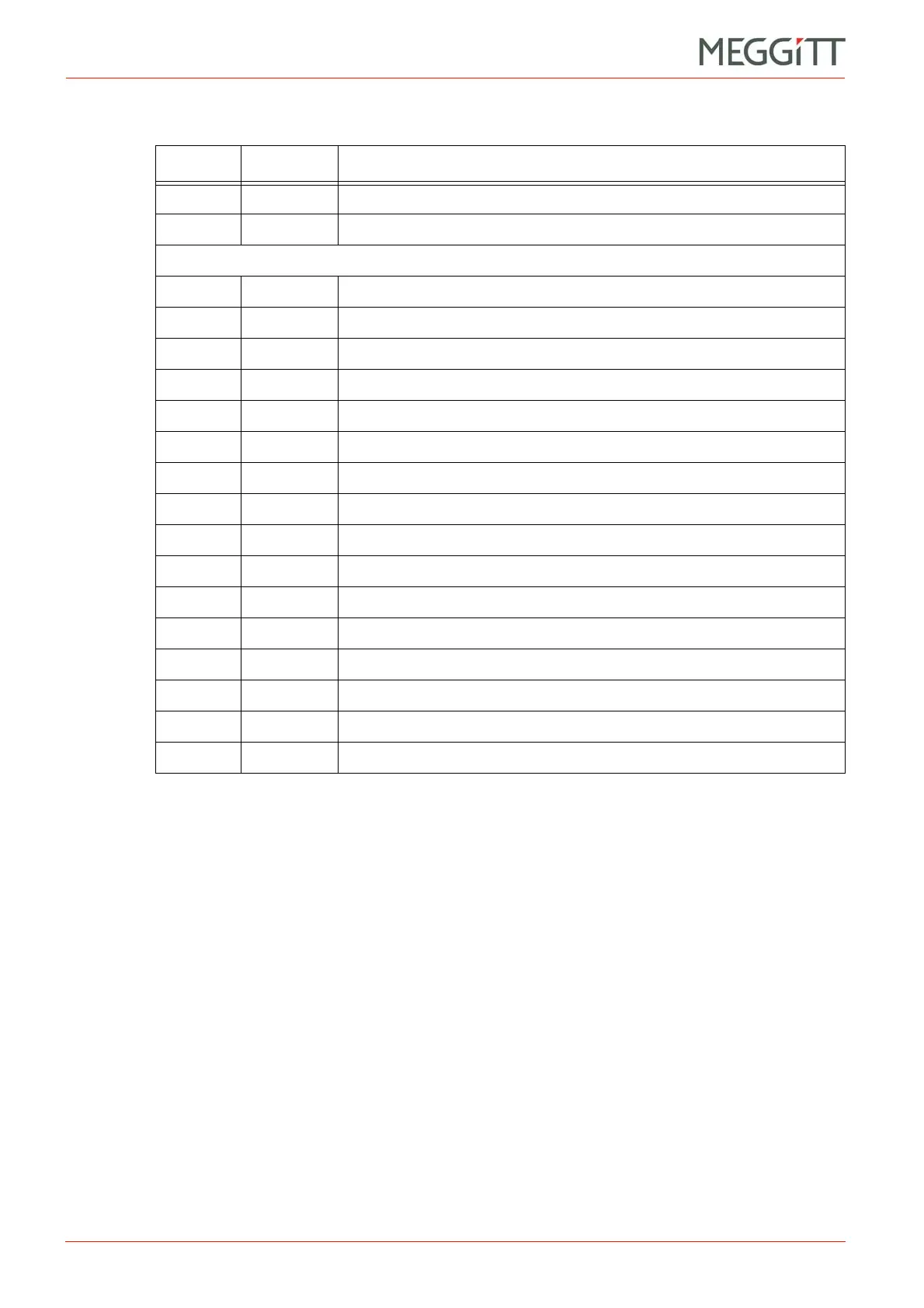
15 RL11 Relay 11 NC
16 RL11 Relay 11 NO
Connector J3
1 RL11 Relay 11 COM
2 RL12 Relay 12 NC
3 RL12 Relay 12 NO
4 RL12 Relay 12 COM
5 RL13 Relay 13 NC
6 RL13 Relay 13 NO
7 RL13 Relay 13 COM
8 RL14 Relay 14 NC
9 RL14 Relay 14 NO
10 RL14 Relay 14 COM
11 RL15 Relay 15 NC
12 RL15 Relay 15 NO
13 RL15 Relay 15 COM
14 RL16 Relay 16 NC
15 RL16 Relay 16 NO
16 RL16 Relay 16 COM
Table 11-1: Definition of terminals for J1, J2 and J3 on the RLC16 card (continued)
Terminal Name Definition

 Loading...


