VM600 MPS hardware manual (standard version) MAMPS-HW/E 9 - 23
Edition 17 - February 2018
Connecting speed sensors
CONFIGURATION OF MPC4 / IOC4T CARDS
9.3.2 Connection diagrams for hardware powered by IOC4T / MPC4
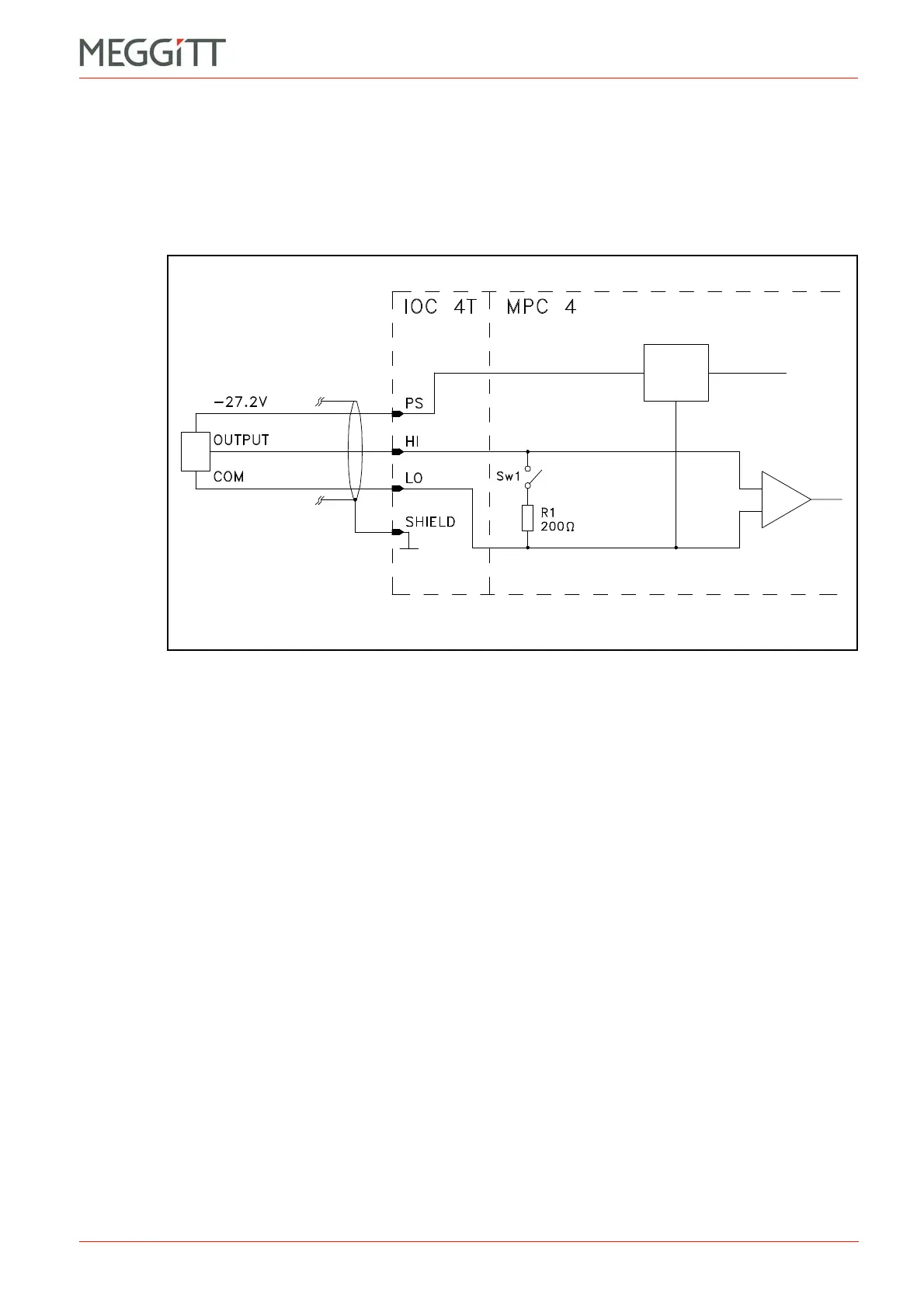
9.3.2.1 Voltage-modulated signal
Applies to the following transducers or transducer and signal conditioner systems:
• TQ4xx + IQS45x.
Notes
1- Switch Sw1 is open to allow voltage-modulated signals to be processed.
For non-Vibro-Meter devices, the Signal Transmission Mode field has to be set to the
Voltage option.
2- The sensor power supply is always set to 27.2 V.
Figure 9-16: Connection diagram
Sensor
power
supply
SPEED
INPUT
(27.2 V only)
 Loading...


