VM600 MPS hardware manual (standard version) MAMPS-HW/E 2 - 15
Edition 17 - February 2018
RLC16 relay card (ABE04x and ABE056)
OVERVIEW OF VM600 MPS HARDWARE
2.8 RLC16 relay card (ABE04x and ABE056)
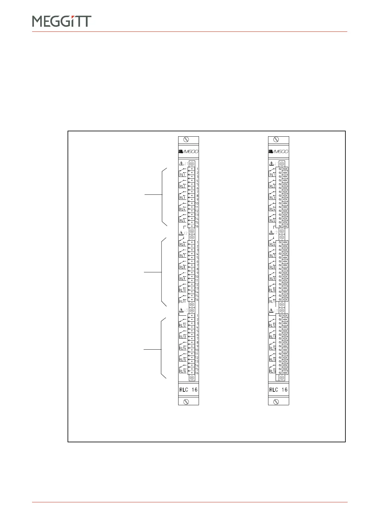
The RLC16 panel (rear of rack) contains three terminal strips, identified as J1, J2 and J3 (see
Figure 2-13). Each strip consists of a socket and a mating connector, which contains 16
screw terminals. The screw terminals can accept wires with a cross section of 1.5 mm
2
.
Figure 2-13 (a) shows the appearance of the RLC16 panel without the three mating
connectors. In this configuration, the engraving showing the terminal definitions is clearly
seen. Figure 2-13 (b) shows the appearance of the panel when the three mating connectors
are inserted.
Figure 2-13: RLC16 panel (rear of ABE04x and ABE056 racks)
(a) (b)
Connector J2
Connector J3
Connector J1
 Loading...


