9 - 44 VM600 MPS hardware manual (standard version) MAMPS-HW/E
Edition 17 - February 2018
Assigning alarm signals to relays on the RLC16 card
CONFIGURATION OF MPC4 / IOC4T CARDS
9.12Assigning alarm signals to relays on the RLC16 card
The IOC4T card contains the following four local relays for signalling alarms: RL1, RL2, RL3
and RL4.
Specific alarms can be attributed to these relays using the VM600 MPSx software.
NOTE: Refer to the relevant manual for further information: VM600 MPS1 software
manual or VM600 MPS2 software manual.
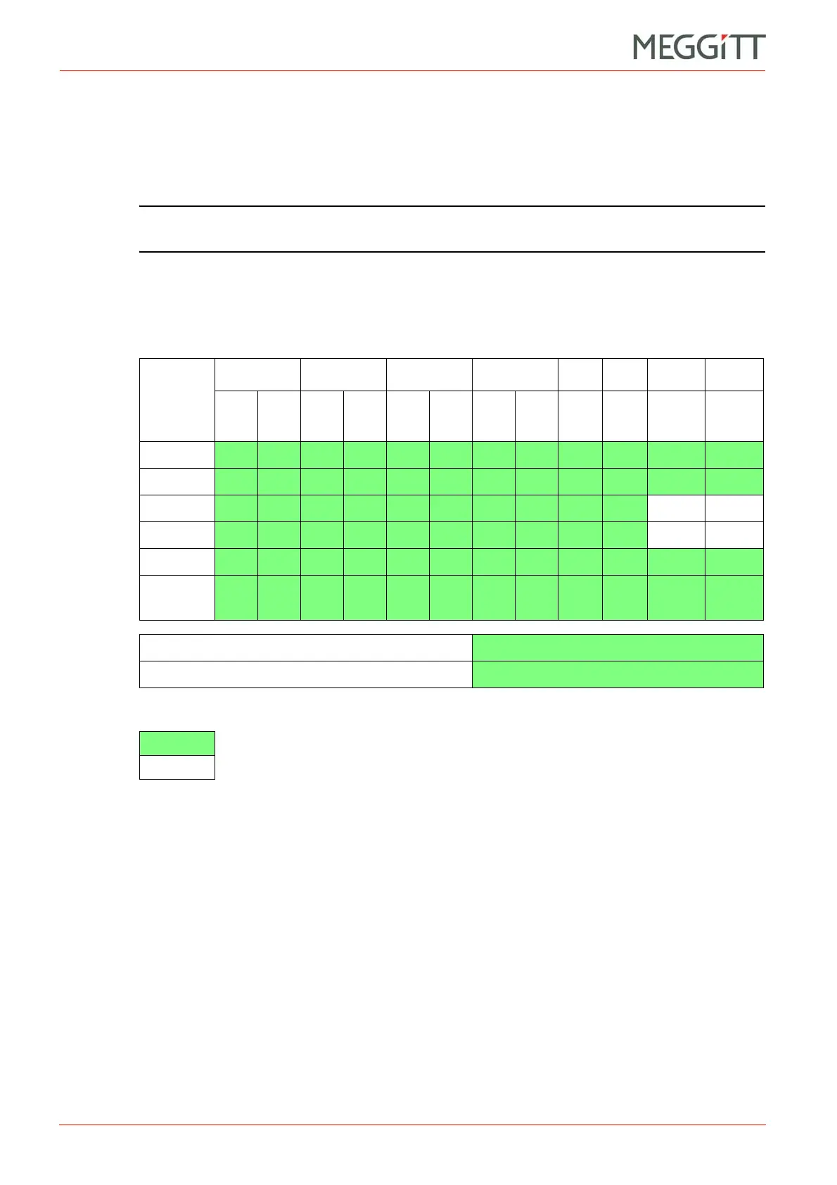
A large number of alarm signals can be processed by the MPS. The possible alarms are
summarised in the table below:
Any of these alarm signals can be sent to the RLC16 card to switch relays. This is achieved
by either of the following two means:
1- Using the Open Collector Bus (OC Bus)
This is the normal method of switching relays. Hardware settings required for this method
are described in Section 9.12.1.
Refer also to 3.4.3 Open Collector Bus for a description of the OC Bus.
2- Using the Raw Bus
This method can be used if the 16 lines provided by the OC Bus are insufficient, or if only
a few relays are required for more than two MPC cards. This method is described in
9.12.2 Using the Raw Bus to switch relays.
Refer also to 3.4.4 Raw Bus for a description of the Raw Bus.
Figure 9-30: Available alarm signals (MPC4 / IOC4T card pair)
Channel 1 Channel 2 Channel 3 Channel 4 Dual Dual Speed Speed
O/P
1
O/P
2
O/P
1
O/P
2
O/P
1
O/P
2
O/P
1
O/P
2
O/P
1&2
O/P
3&4
O/P
1
O/P
2
Alert+
Alert
Danger+ N/A N/A
Danger
N/A N/A
OK level
Channel
Status *
Basic logical combinations of alarms
Up to 8 possibilities
Advanced logical combinations of alarms
Up to 4 possibilities
Key:
= Alarm available
N/A = Alarm not available
* Channel Status = Processing Error, Track Lost and so on
 Loading...


