VM600 MPS hardware manual (standard version) MAMPS-HW/E 9 - 45
Edition 17 - February 2018
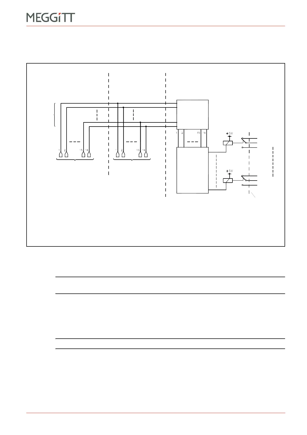
Assigning alarm signals to relays on the RLC16 card
CONFIGURATION OF MPC4 / IOC4T CARDS
9.12.1 Using the Open Collector Bus (OC Bus) to switch relays
Figure 9-31 shows the operating principle when the OC Bus is used to switch relays.
The attribution of a specific alarm signal (generated by the MPC4 / IOC4T cards) to a control
signal line (and therefore to an OC Bus line) is done using the VM600 MPSx software.
NOTE: Refer to the relevant manual for further information: VM600 MPS1 software
manual or VM600 MPS2 software manual.
The attribution of a specific line on the OC Bus to a specific relay on the RLC16 is done by
setting a jumper on the RLC16 card. Additional jumpers allow the selection of relay normally
energised (NE) or normally de-energised (NDE). The jumper settings are summarised in
Table 9-7 and the position of the relevant jumpers on the RLC16 card is shown in
Figure 9-33.
NOTE: See 3.4.3 Open Collector Bus for further information on the OC Bus.
Figure 9-31: Using the Open Collector Bus (OC Bus) to switch relays
Relay 1
Relay 16
RLC16
panel
Jumpers
to select
NE/NDE
Jumper
matrix
(on RLC16)
Control signals
(see note 1)
Control signals
(see note 1)
OC Bus
(16 lines)
IOC in slot nIOC in slot n+1
RLC in slot m
n = {3, 5, 7, 9, 11 or 13}
m = {1, 2, 15, 16, 17 or 18}
n = {3, 5, 7, 9, 11 or 13}
Notes
1. Specific alarms (A+, D and so on) are attributed to the OC Bus lines using the
VM600 MPSx software. See Table 9-4 for information on the normal state of
the control signal.
 Loading...


