13 - 2 VM600 MPS hardware manual (standard version) MAMPS-HW/E
Edition 17 - February 2018
Configuring RS serial communications
CONFIGURATION OF CPUM / IOCN CARDS
13.2Configuring RS serial communications
Secondary serial communications (RS-232 or RS-485) via the ‘RS’ connector on the IOCN
card’s panel is configured using jumpers on the CPUM card.
13.2.1 RS-232 selection
This is the simplest configuration as the lines coming from the PC/104 CPU module are
routed directly to the P2 connector.
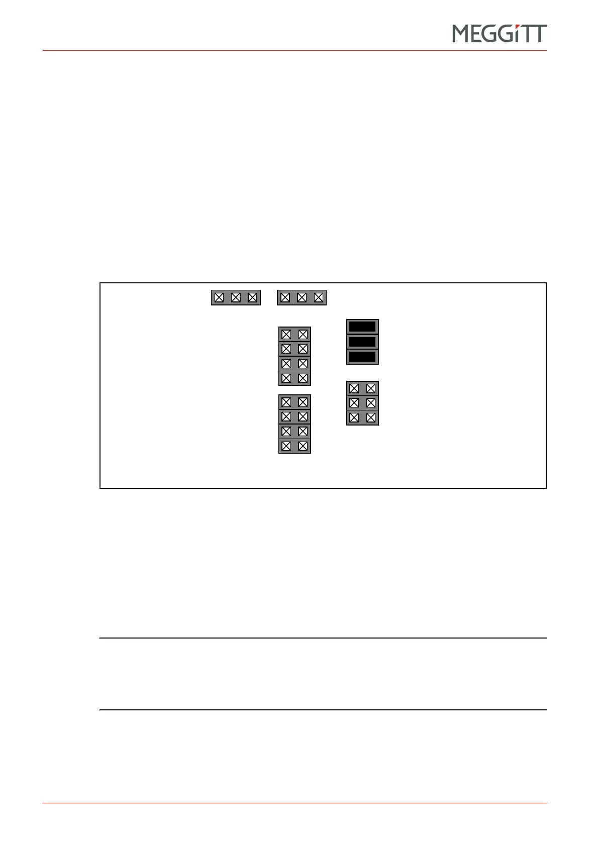
RS-232 communication is configured by bypassing the RS-232 to RS-485 converter on the
CPUM card. The converter is switched out using jumpers J43, J45 and J41 (see Figure 13-2).
The location of the jumpers on the CPUM card can be found using Figure 13-13 or
Figure 13-14.
13.2.2 RS-485 selection, half-duplex (2-wire) configuration
Half-duplex (2-wire) RS-485 communications is configured by using the RS-232 to RS-485
converter on the CPUM card. The converter is switched in using jumpers J28, J29, J44, J46
and J39 (see Figure 13-3).
Jumpers J31 to J34 can also be set if terminations are needed (see Figure 13-9).
The location of the jumpers on the CPUM card can be found using Figure 13-13 or
Figure 13-14.
NOTE: In the Meggitt Sensing Systems’ factory, the default configuration for CPUM/IOCN
card pairs is full-duplex RS-485, with each differential pair terminated with a 120
resistor (see case (b) of Figure 13-9).
CPUM and IOCN card pairs will be delivered with the default configuration, unless
a different one is specified by the customer.
J34
J33
J32
J31
J28
J29
J38
J37
J36
J35
J43
J45
J41
J44
J46
J39
Figure 13-2: CPUM card jumper settings to select RS-232 (RS connector)

 Loading...


