13 - 12 VM600 MPS hardware manual (standard version) MAMPS-HW/E
Edition 17 - February 2018
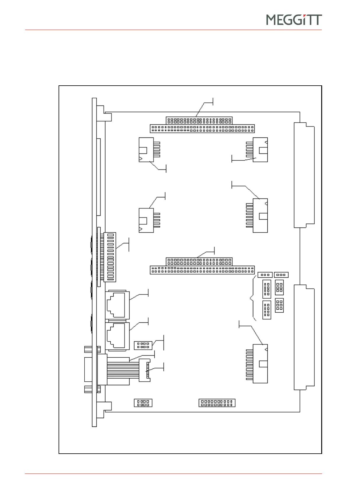
Location of components on the CPUM card (later PFM-541I version)
CONFIGURATION OF CPUM / IOCN CARDS
13.7Location of components on the CPUM card (later PFM-541I version)
Figure 13-13 shows the position of jumpers and large components on later versions of the
CPUM card (PNR 200-595-076-HHh or later) designed to be fitted with the PFM-541I or
equivalent CPU module (see 6.1 Different versions of the CPUM card).
Figure 13-13: Location of jumpers on the CPUM card (later PFM-541I version)
J1
(P1)
J13
J21
(COM2)
J28 J29
J34
J33
J32
J31
J38
J37
J36
J35
J43
J45
J41
J44
J46
J39
J53
J52
J40
J42
PC /104 slot 1
(J11 and J13)
J2
(P2)
J16
(COM1)
PC /104 slot 2
(J10 and J12)
RS-232 and
RS-485
jumpers
J20
(RS-485)
J48
(ETH1)
J47
(ETH0/rear)
Ethernet
front/rear
jumpers
J11
J10
J12
J4 and J5
(To display and
buttons on panel)
J15 (ETH0/front) – NET
J14 (COM0) – RS232
J3
(ISA address
jumpers)
J8
(ISA interrupt
jumpers – not used)
CPUM
panel
RS-232
NET

 Loading...


