10 - 8 VM600 MPS hardware manual (standard version) MAMPS-HW/E
Edition 17 - February 2018
Connecting sensors to the IOC8T
CONFIGURATION OF AMC8 / IOC8T CARDS
10.2.3 Connecting RTD devices
An RTD (resistance temperature detector) is a metal wire resistor whose resistance varies
with temperature in a precisely known manner. A known current is injected into the device
and the resulting voltage across the resistor is measured.
Several connection possibilities exist:
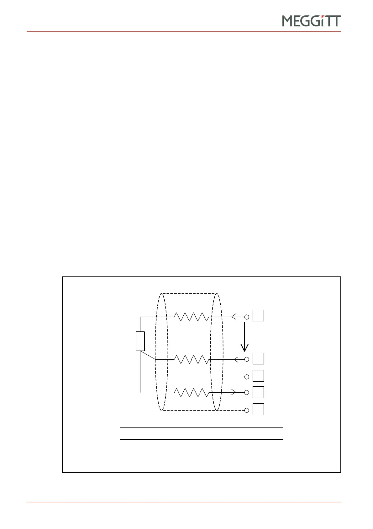
1- 3-wire connection (see Figure 10-5)
This is the most common arrangement and takes the form of a bridge connection. It
requires a shielded, 3-core cable. It uses two equal injection currents (i1 and i2) which
allow compensation of the opposing voltages on RL1 and RL2. It is insensitive to line
resistance provided that RL1 = RL2 and i1 = i2.
A disadvantage of the technique is that corroded contacts can make RL1 and RL2
different, thereby inducing measurement errors.
2- 2-wire connection (see Figure 10-6)
This is the worst arrangement as it is very sensitive to line resistance. Despite this, it is
quite commonly used with RTDs having a low resistance value (for example, Cu10). It is
often built into the stator of old hydro alternators. The 2-wire technique demands high
performance on the part of the measuring chain.
3- 4-wire connections (see Figure 10-7)
This arrangement (also known as “Kelvin connection”) is the best and the least sensitive
to disturbances. The current path and voltage path are well separated. The arrangement
is insensitive to corroded contacts.
In the 3-wire plus shield arrangement (case (a) of Figure 10-7), the measuring current return
flows through the shield. In terms of EMC, this is less favourable than the true 4-wire
arrangement (case (b) of Figure 10-7).
Figure 10-5: 3-wire RTD connection
NOTE: The setting of jumper J805 is unimportant.
 Loading...


