VM600 MPS hardware manual (standard version) MAMPS-HW/E 5 - 7
Edition 17 - February 2018
Alarm monitoring
AMC8 / IOC8T CARD PAIR
5.7 Alarm monitoring
5.7.1 Monitoring possibilities
For each single channel or “multi-channel”, the AMC8 can compare the measured value
against user-configurable Alert and Danger levels. For each of these, a high limit and a low
limit can be set:
• Danger+, the upper Danger level (for an increasing signal)
• Alert+, the upper Alert level (for an increasing signal)
•Alert, the lower Alert level (for a decreasing signal)
• Danger, the lower Danger level (for a decreasing signal).
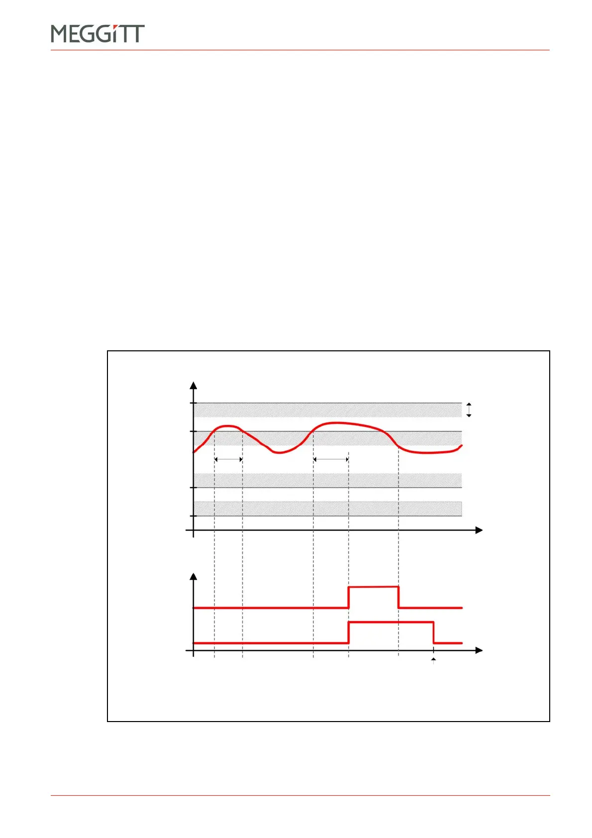
A time delay (t) can be software configured for each Alert or Danger level. The signal level
must be over (or under, in the case of low-level alarms) the alarm level (including the
hysteresis value) for more than t before an alarm is generated.
A hysteresis value can be software configured for each Alert or Danger level.
The alarm events can be latched if required. The alarm latches can be reset either externally
or via the CPUM card (if installed).
The example given in Figure 5-3 illustrates alarm latching when t = 3 seconds.
Figure 5-3: Illustration of unlatched and latched alarms
Signal level
Time
Hysteresis
Normal Alarm Normal
Normal Alarm Normal
Alarm Reset
A+ status
unlatched
A+ status
latched
Time
D+
A+
A
D
t 3st < 3 s

 Loading...


