2 - 16 VM600 MPS hardware manual (standard version) MAMPS-HW/E
Edition 17 - February 2018
IRC4 intelligent relay card (ABE04x and ABE056)
OVERVIEW OF VM600 MPS HARDWARE
2.9 IRC4 intelligent relay card (ABE04x and ABE056)
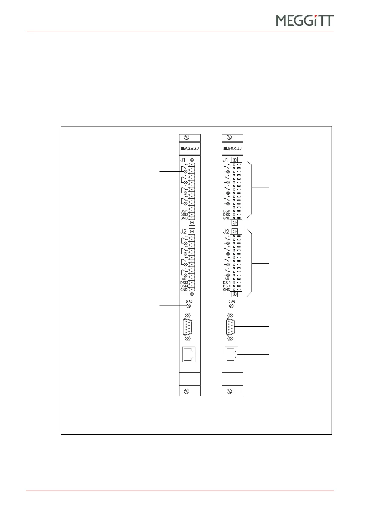
The IRC4 panel (rear of rack) contains two terminal strips, identified as J1 and J2 (see
Figure 2-14). Each strip consists of a socket and a mating connector, which contains 16
screw terminals. The screw terminals can accept wires with a cross section of 1.5 mm
2
.
Figure 2-14 (a) shows the appearance of the IRC4 panel without the 2 mating connectors. In
this configuration, the engraving showing the terminal definitions is clearly seen.
Figure 2-14 (b) shows the appearance of the panel when the 2 mating connectors are
inserted.
IRC 4
RL Y1
RLY2
RL Y3
RL Y4
DB
RL Y5
RL Y6
RL Y7
RL Y8
IRC 4
RL Y1
RLY2
RL Y3
RL Y4
DB
RL Y5
RL Y6
RL Y7
RL Y8
Figure 2-14: IRC4 panel (rear of ABE04x and ABE056 racks)
Connector J2
(Not used)
Connector J1
(a) (b)
RS-232 connector for
local configuration
DIAG indicator.
The colours of the LED have the following
significance:
* Green – The card is in the correct slot
* Red – Slot number mismatch or HW
error.
(Same function as the SLOT ERROR LED
on other cards.)
Status indicator for relay 1.
The colours of the LED have the
following significance:
* Green – Result of the relay’s logic
equation is false
* Red – Result of the relay’s logic
equation is true
* Yellow blinking – Relay error.
Operation of status indicators for
relay 2 to relay 8 are as for relay 1.
 Loading...


