9 - 26 VM600 MPS hardware manual (standard version) MAMPS-HW/E
Edition 17 - February 2018
Connecting speed sensors
CONFIGURATION OF MPC4 / IOC4T CARDS
9.3.4 Connection diagrams for externally powered hardware
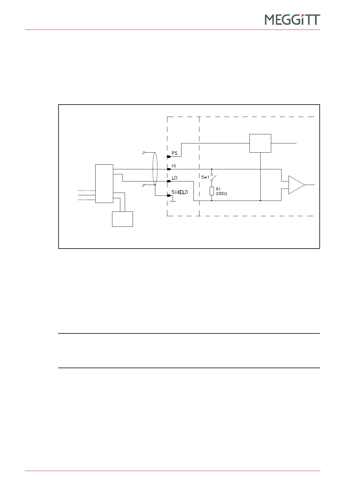
9.3.4.1 Voltage-modulated signal with GSI127 galvanic separation unit
Applies to the later versions of the following transducers or transducer and signal conditioner
systems:
• TQ4xx + IQS45x + GSI127 galvanic separation unit.
Notes
1- Switch Sw1 is open to allow voltage-modulated signals to be processed.
The Signal Transmission Mode field has to be set to the Voltage option.
2- The operator must connect an external power supply to terminals “24 VDC +” and
“24 VDC ” of the GSI127 galvanic separation unit.
3- The sensor power supply is always set to 27.2 V.
NOTE: More detailed information on connecting equipment to an electronic monitoring
system can be found in the project-specific wiring diagram delivered with the
system or by referring to the electrical connections (wiring diagrams) section of the
appropriate sensors and signal conditioners installation manual.
Figure 9-19: Connection diagram
Sensor
power
supply
SPEED
INPUT
External
power
supply
(27.2 V only)
O/P
0V
()
+
SIGNAL24 VDC
GSI127
I/P
/COM
+/COM
From sensor (transducer)
or measurement chain
IOC4T MPC4
(+)
 Loading...


