VM600 MPS hardware manual (standard version) MAMPS-HW/E 9 - 27
Edition 17 - February 2018
Connecting speed sensors
CONFIGURATION OF MPC4 / IOC4T CARDS
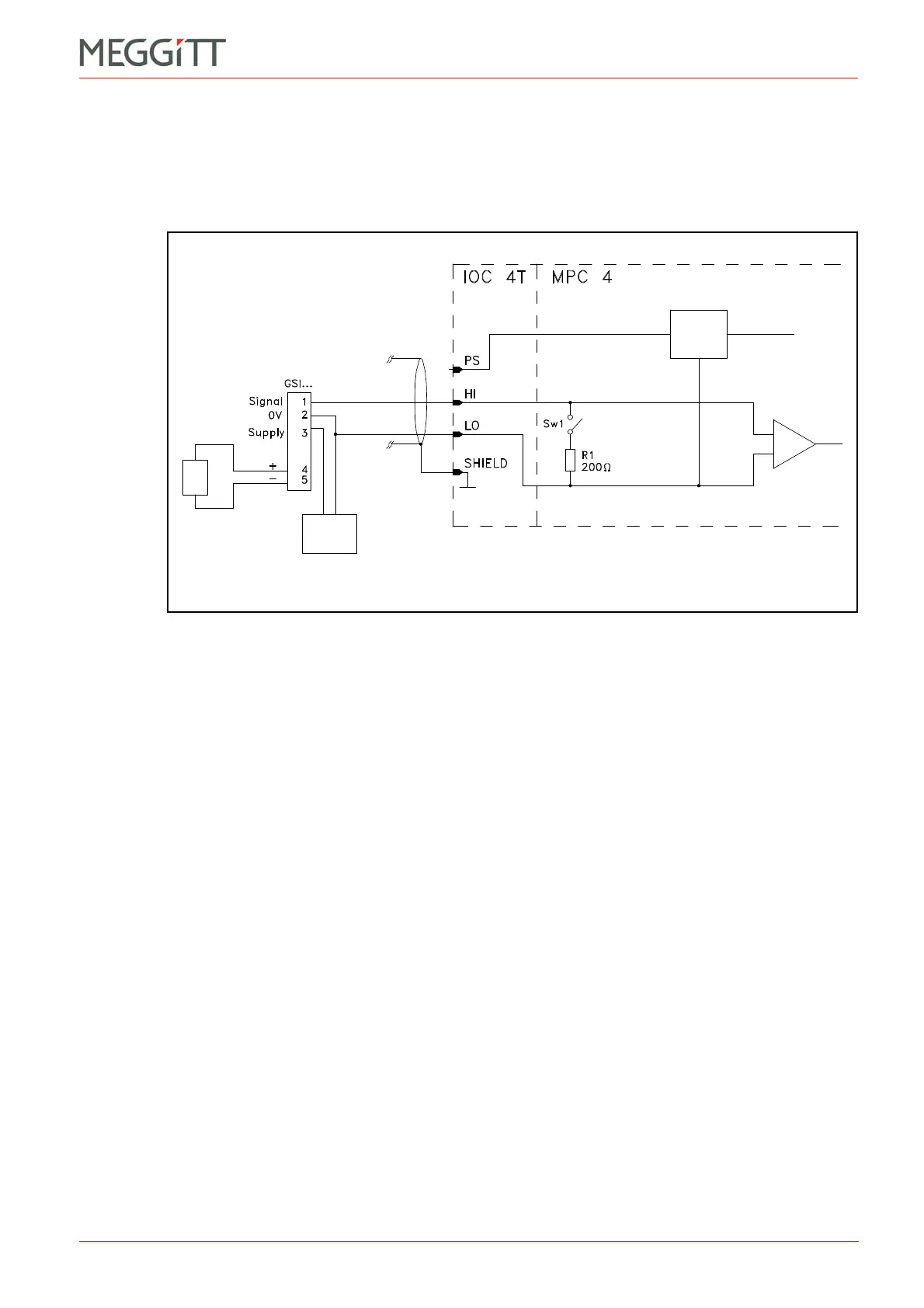
9.3.4.2 Voltage-modulated signal with GSIxxx galvanic separation unit
Applies to the earlier versions of the following transducers or transducer and signal
conditioner systems:
• TQ4xx + IQS45x + GSIxxx galvanic separation unit.
Notes
1- Switch Sw1 is open to allow voltage-modulated signals to be processed.
The Signal Transmission Mode field has to be set to the Voltage option.
2- The operator must connect an external power supply to terminals 2 and 3 of the GSIxxx
galvanic separation unit.
3- The sensor power supply is always set to 27.2 V.
Figure 9-20: Connection diagram
Sensor
power
supply
SPEED
INPUT
External
power
supply
(27.2 V only)
 Loading...


