7 - 10 VM600 MPS hardware manual (standard version) MAMPS-HW/E
Edition 17 - February 2018
Position measurement
PROCESSING MODES AND APPLICATIONS
7.6 Position measurement
(1) Description
The relative position of a shaft can be measured by placing a proximity probe on the bearing.
This type of measurement is particularly applicable to fluid-film thrust bearings where it is
necessary to measure the axial motion of the shaft relative to the bearing.
The following front-end components are the most commonly used:
• TQxxx proximity transducer + IQSxxx signal conditioner
• TQxxx proximity transducer + IQSxxx signal conditioner + (Intrinsically safe) GSVxxx
power supply and safety barrier (applications).
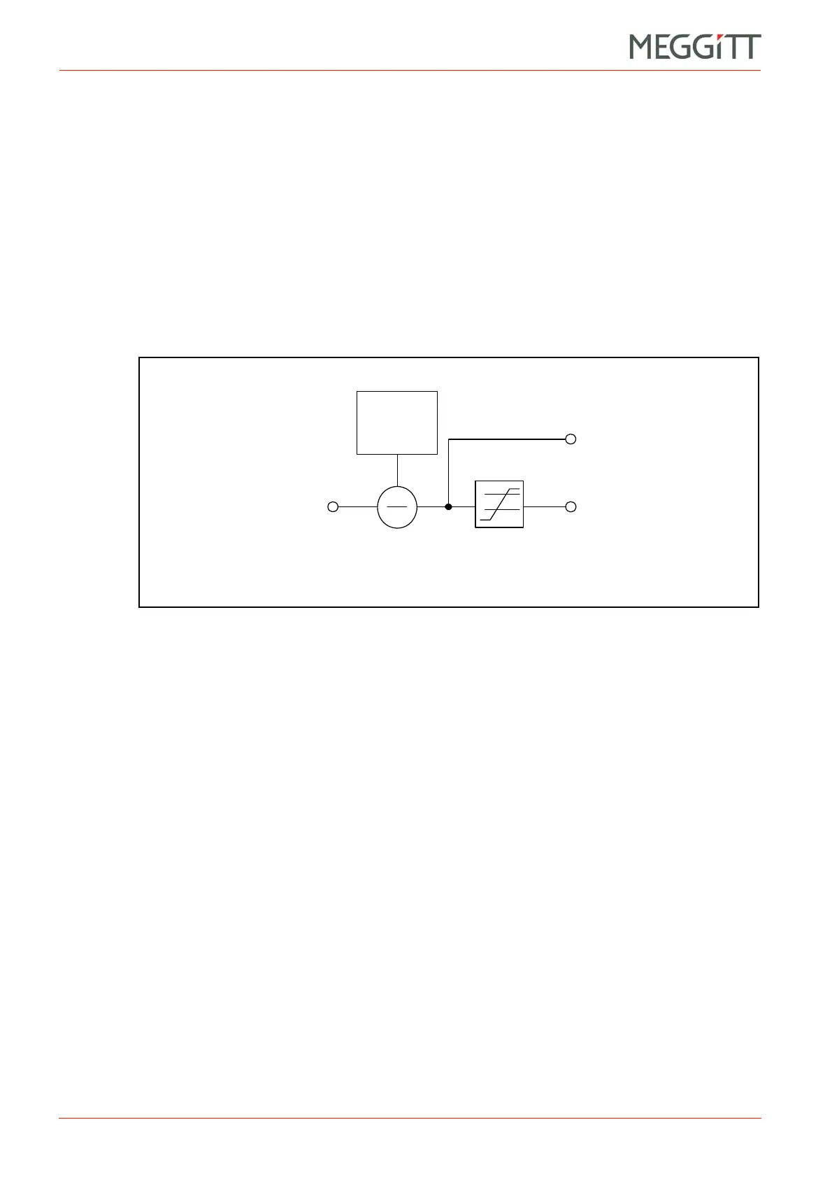
(2) Block diagram
With a proximity probe connected to the MPS, the position processing function calculates the
position of the target relative to a reference point.
The initial target position (gap) must be stored (or configured). This will be used as a
reference position for measurement purposes. This value ( X
initial
) depends on the physical
probe placement, and must be subtracted from the measured value ( X
in
) in order to give
the target position relative to the reference position:
X
out
= X
in
X
initial
7.7 S
max
measurement
(1) Description
S
max
is a vibration measurement used in machinery monitoring systems, defined in
ISO 7919-1 as the maximum vibratory displacement in the plane of measurement.
S
max
monitoring is a special case of shaft relative vibration monitoring that measures the
radial motion of the shaft. Like shaft relative vibration, it is typically measured using two
proximity transducers (X and Y) mounted on the machine bearing at approximately 90° to
each other (see Figure 7-8).
In general, the two proximity transducer (X and Y) values are added vectorially to provide the
S
max
(maximum displacement) value as defined in ISO 7919-1. However, there are different
methods of calculating S
max
, defined as methods A, B and C in ISO 7919-1 Annex B.
Figure 7-7: Block diagram showing position processing
Position value
( X
out
)
Alarms
Position input
( X
in
)
Initial gap
(X
initial
)
 Loading...


