VM600 MPS hardware manual (standard version) MAMPS-HW/E 2 - 7
Edition 17 - February 2018
MPC4 machinery protection card (ABE04x and ABE056)
OVERVIEW OF VM600 MPS HARDWARE
2.2 MPC4 machinery protection card (ABE04x and ABE056)
The MPC4 card has the following panel elements (see Figure 2-7):
1- One global DIAG/STATUS indicator for the MPC4
/ IOC4T card pair
This multi-coloured, multi-function LED is used to indicate:
• The status of the card configuration
• Whether special functions such as Trip Multiply (TM) or Danger Bypass (DB) are
in use
• An MPC4 card failure due to a hardware or a software problem.
2- BNC connectors RAW OUT 1 to RAW OUT 4
A connector is present for each of the four measurement channels. Used to output raw
analog signals (corresponding to, for example, vibration or dynamic pressure).
3- BNC connectors TACHO OUT 1 and TACHO OUT 2
A connector is present for each of the two rotational speed channels. Used to output
speed/phase reference signals. These signals are TTL-conditioned.
4- Status indicators for the four measurement channels and the 2 rotational speed channels
Each multi-coloured, multi-function LED is used to indicate:
• Whether the signal input for that channel is valid
• The presence of an incoming signal in the Alert/Danger condition
• Whether the channel inhibit function is in use.
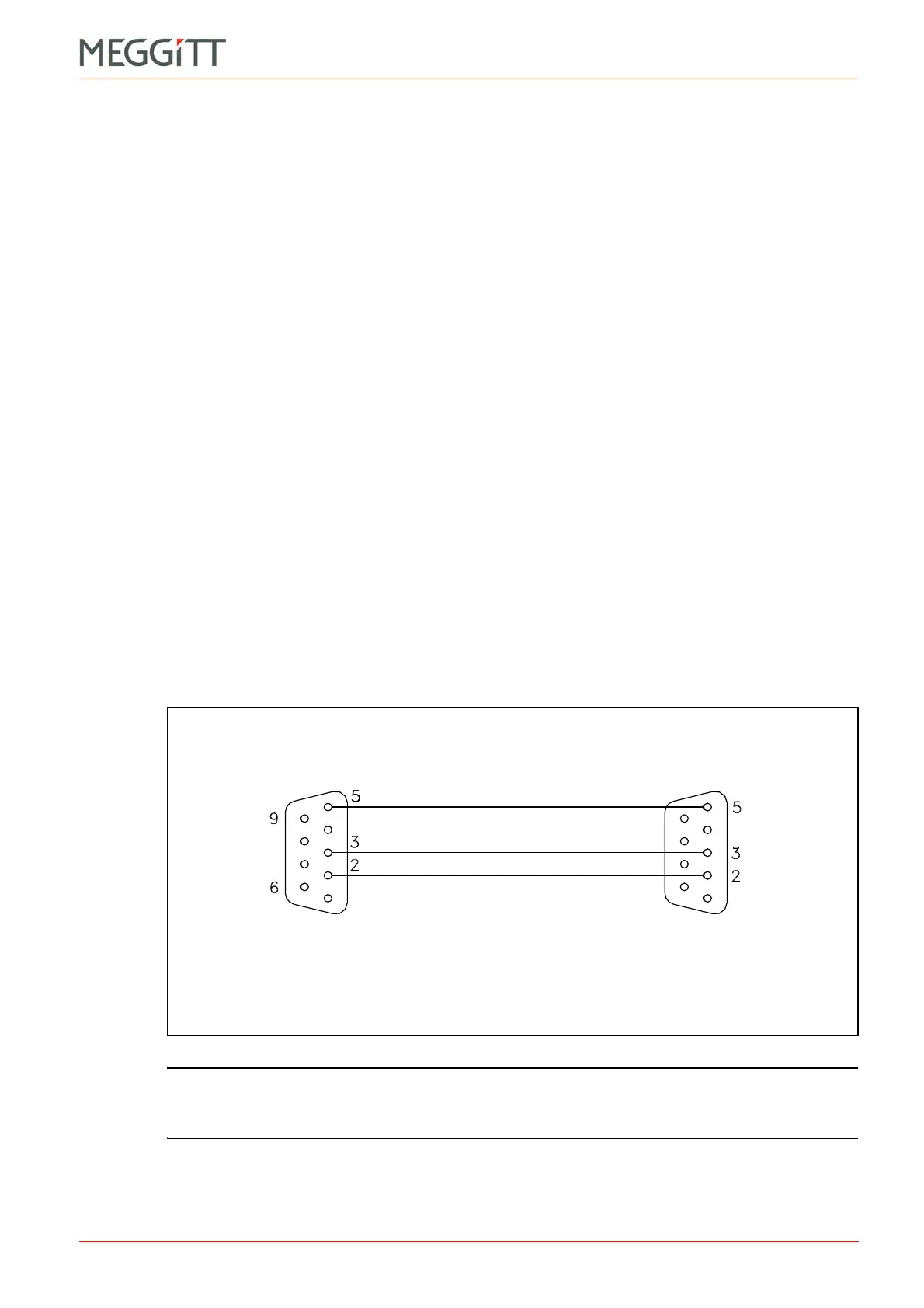
5- RS-232 connector
This
9-pin D-sub connector can be used to configure an MPC4 card in a stand-alone rack.
This is done via an interface cable from a computer running one of the VM600 MPS
software packages (MPS1 or MPS2). See Figure 2-6 for details of the interface cable.
NOTE: The MPC4 machinery protection card is available in different versions, including a
standard version, a separate circuits version and a safety (SIL) version.
See 4 MPC4 / IOC4T card pair for additional information.
Figure 2-6: Interface cable used to connect the MPC4 (or AMC8) card to the
serial port of a computer running the configuration software
Connect to
MPC4 card
Male
connector
Female
connector
Connect to
computer
 Loading...


