VM600 MPS hardware manual (standard version) MAMPS-HW/E 12 - 1
Edition 17 - February 2018
General block diagram
USING THE IRC4 CARD
12 USING THE IRC4 CARD
This chapter describes the connectors on the IRC4 card. These are accessed from the rear
of a VM600 MPS rack.
Information is also given on attributing specific alarm signals to specific relays on IRC4 cards
using the Open Collector Bus and the Raw Bus.
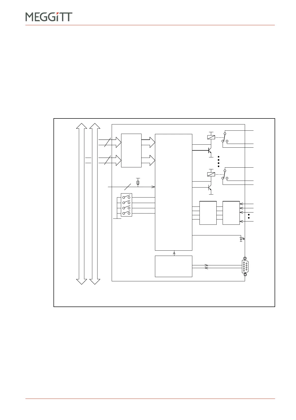
12.1General block diagram
A block diagram of the IRC4 card is shown in Figure 12-1. It shows an IRC4 installed in the
rear of a rack and connected to the Raw and OC buses.
12.2Definition of the screw terminals on the IRC4 card
The IRC4 panel (rear of rack) card contains two terminal strips, J1 and J2 (see Figure 12-2).
Each strip consists of a socket and a mating connector, which contains 16 screw terminals.
The screw terminals can accept wires with a cross section of 1.5 mm
2
.
Each socket and mating connector can be equipped with a mechanical key system to prevent
incorrect connection.
Further details on the connectors can be found in Table 12-1.
Figure 12-1: Block diagram of the IRC4 card
Rack slot number (connector P4)
Raw Bus (connector P3)
Input
protection
16
OC Bus (connector P3)
64
4
8x
Slot number
(micro-switch)
Micro-controller
Logic
Schmitt
triggers
Input
protection
RLY8 RLY1
DIAG
DB
AR
DSI 1
DSI 4

 Loading...


