VM600 MPS hardware manual (standard version) MAMPS-HW/E 12 - 3
Edition 17 - February 2018
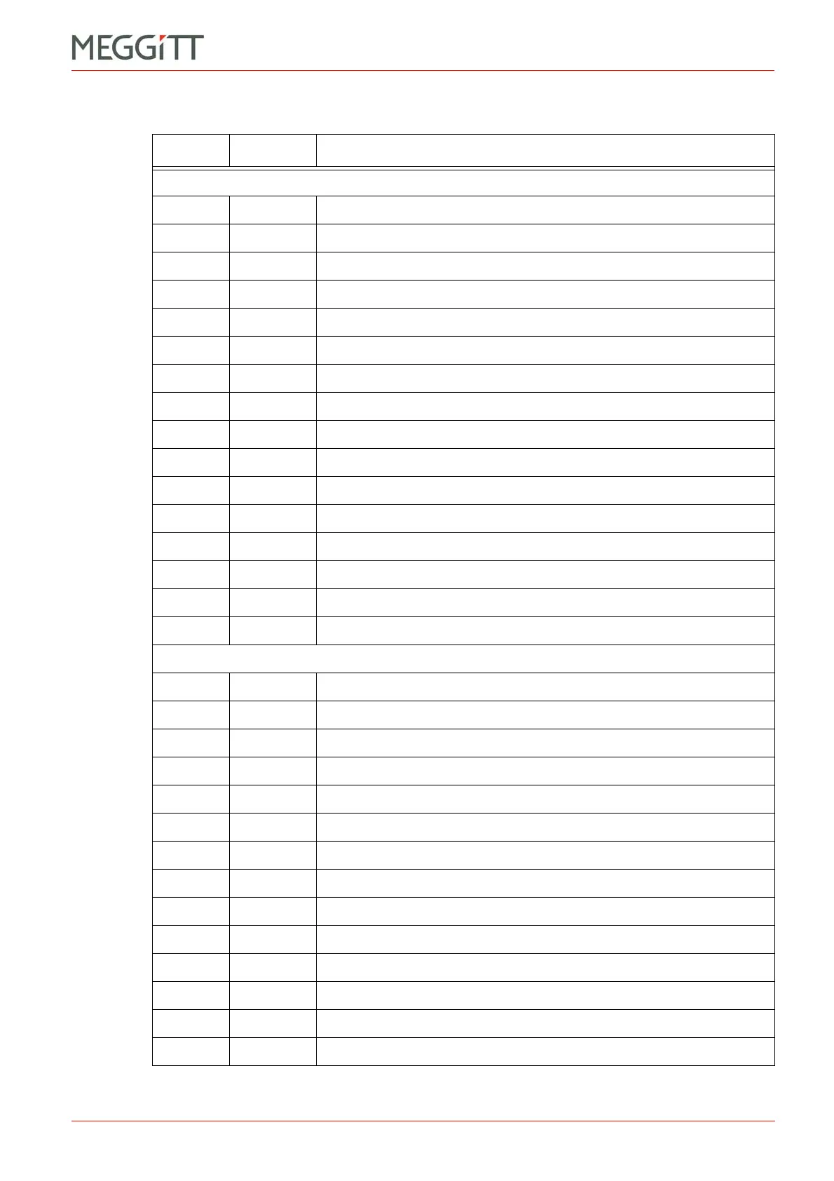
Definition of the screw terminals on the IRC4 card
USING THE IRC4 CARD
Table 12-1: Definition of connectors on the IRC4 card
Terminal Name Definition
Connector J1
1 RL1 Relay 1 NO (normally open) contact
2 RL1 Relay 1 NC (normally closed) contact
3 RL1 Relay 1 COM contact
4 RL2 Relay 2 NO
5 RL2 Relay 2 NC
6 RL2 Relay 2 COM
7 RL3 Relay 3 NO
8 RL3 Relay 3 NC
9 RL3 Relay 3 COM
10 RL4 Relay 4 NO
11 RL4 Relay 4 NC
12 RL4 Relay 4 COM
13 DB Danger Bypass input (control line)
14 DSI1 Discrete signal interface control input 1 (control line)
15 DSI2 Discrete signal interface control input 2 (control line)
16 GND Chassis ground (return line for DB, AR and other DSI inputs)
Connector J2
1 RL5 Relay 5 NO
2 RL5 Relay 5 NC
3 RL5 Relay 5 COM
4 RL6 Relay 6 NO
5 RL6 Relay 6 NC
6 RL6 Relay 6 COM
7 RL7 Relay 7 NO
8 RL7 Relay 7 NC
9 RL7 Relay 7 COM
10 RL8 Relay 8 NO
11 RL8 Relay 8 NC
12 RL8 Relay 8 COM
13 AR Alarm Reset input (control line)
14 DSI3 Discrete signal interface control input 3 (control line)
 Loading...


