VM600 MPS hardware manual (standard version) MAMPS-HW/E 9 - 9
Edition 17 - February 2018
Connecting vibration and pressure sensors
CONFIGURATION OF MPC4 / IOC4T CARDS
The Sensor Connected field has no direct influence on the setting of Sw1 and Sw2. The field
can be considered as a comment for the user. When it is set to "No", the other fields in this
VM600 MPS software window will be unavailable (that is, appear greyed out), but the values
and settings will still be effective.
NOTE: For all devices (Meggitt Sensing Systems’ Vibro-Meter products and competitor
products), the Sensor Power Supply field has to be set to one of the voltage
values (No Supply, +27 VDC, −27 VDC, +15 VDC or +6.16 mA). Any one of these
settings can be chosen.
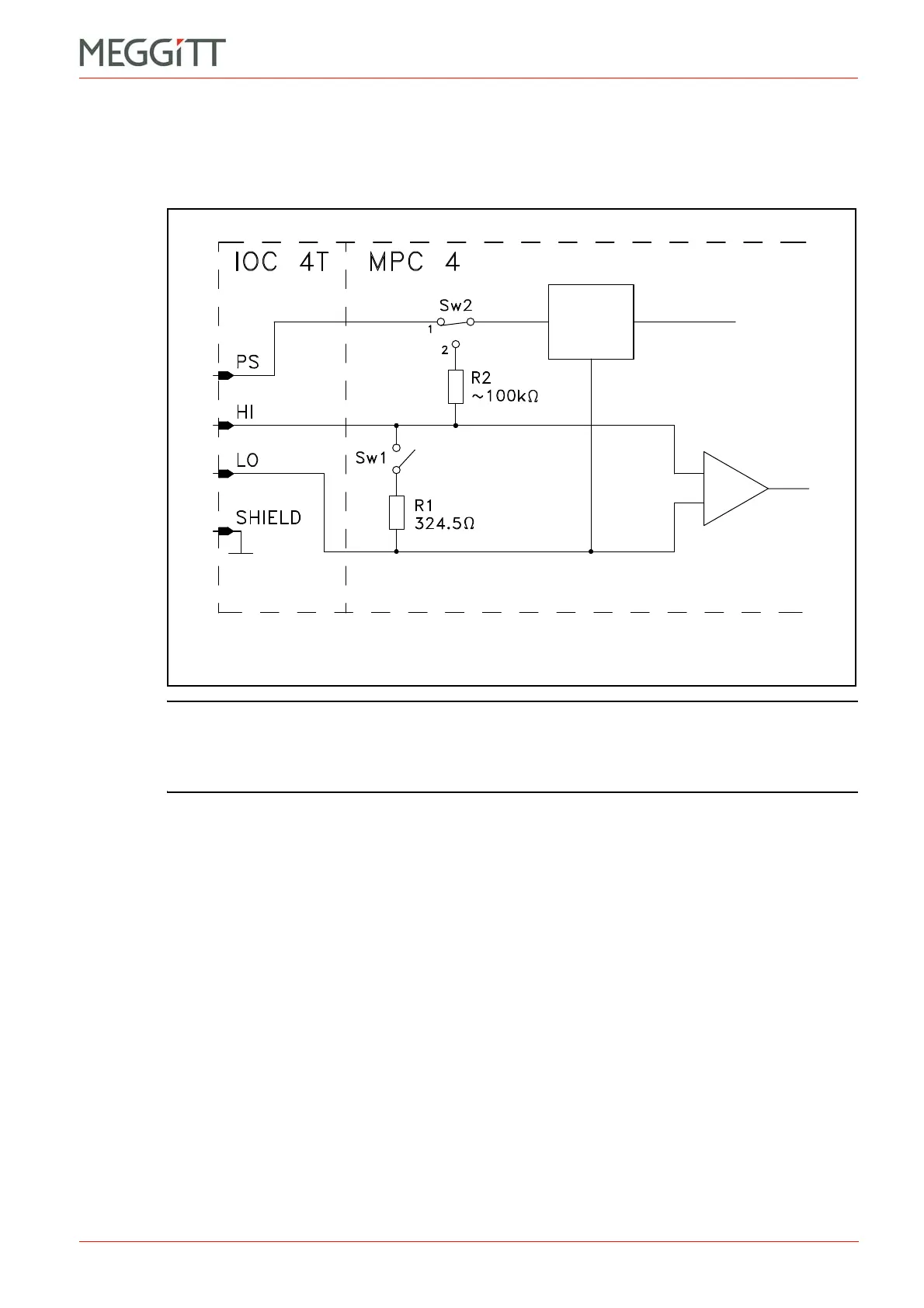
Figure 9-3: Circuitry associated with measurement channel inputs
Sensor
power
supply
 Loading...


