7 - 30 VM600 MPS hardware manual (standard version) MAMPS-HW/E
Edition 17 - February 2018
Dual mathematical function
PROCESSING MODES AND APPLICATIONS
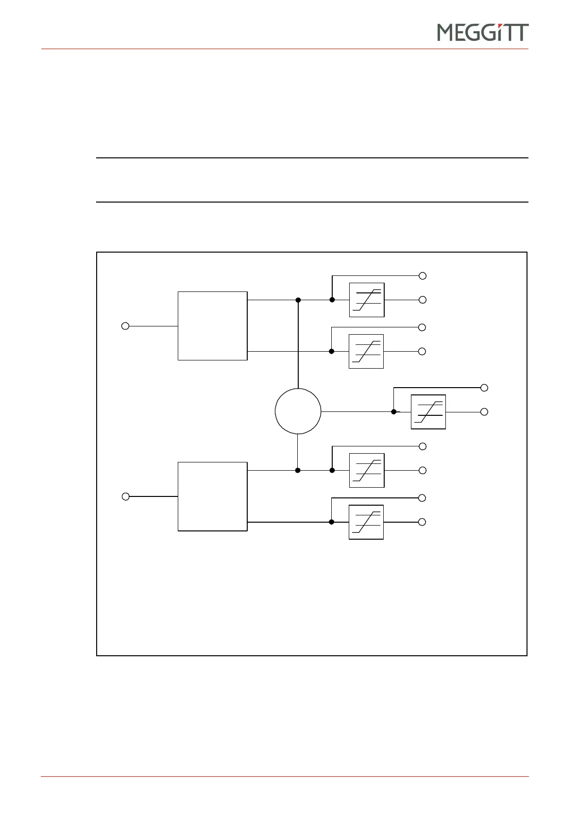
As shown in Figure 7-28 as Out 1, dual mathematical function processing only operates on
the first processed outputs from the single-channel processings:
• DMF for Measurement Input Channels 1 & 2 operates on the first processed outputs of
Channel 1 and Channel 2.
• DMF for Measurement Input Channels 3 & 4 operates on the first processed outputs of
Channel 3 and Channel 4.
NOTE: The Dual mathematical function processing implemented on VM600 MPC4 cards
can be configured as X & Y MAX in order to use ISO 7919-1 method B to calculate
an S
max
value. See also 7.7 Smax measurement.
(2) Block diagram
Input 1
Figure 7-28: Block diagram showing DMF processing
Alarm level
detectors
DMF
DMF value
DMF alarms
Note: The DMF (dual mathematical function) processing function can be: RMS Sum,
RMS Subtraction, SUM, SUBTRACTION, X & Y MAX or X & Y MIN.
Single-channel
processing
(Channel 1 or
Channel 3)
Single-channel
processing
(Channel 2 or
Channel 4)
Input 2
(Out 1)
(Out 2)
(Out 1)
(Out 2)
Output 1 value
Output 1 alarms
Output 2 value
Output 2 alarms
Output 1 value
Output 1 alarms
Output 2 value
Output 2 alarms
 Loading...


