7 - 4 VM600 MPS hardware manual (standard version) MAMPS-HW/E
Edition 17 - February 2018
Broad-band absolute bearing vibration
PROCESSING MODES AND APPLICATIONS
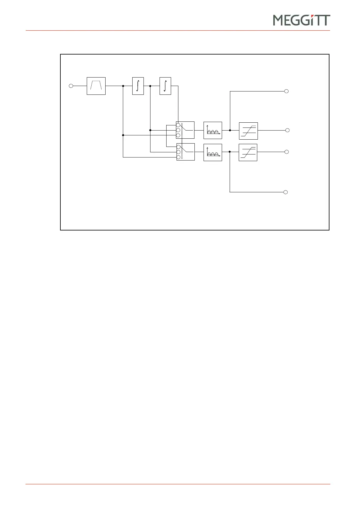
(2) Block diagram
Principal features:
• Configurable band-pass filtering (HP/LP) from 0.1 Hz to 10 kHz
• LP/HP ratio: up to 500 (up to 100 with double integration)
• Slope: up to 60 dB/octave
• Cut-off frequency: defined at 0.1 dB
• Unity gain: max. ±0.3 dB
• Pass-band ripple: max. ±0.1 dB
• Stop-band rejection: min. 50 dB
• Acceleration output (g or m/s
2
or inch/s
2
)
• Velocity value processing (g or m/s
2
or inch/s
2
converted to mm/s or inch/s)
• Displacement value processing (g or m/s
2
or inch/s
2
converted to mm or mils).
Between 3 kHz and 10 kHz there can be some restrictions on the LP/HP ratio and filter slope
due to the demand on processing power required by the four MPC channels. Depending on
the MPC configuration, simultaneous processing on all four channels may cause processing
overload. See 14.7 Checking the MPC4 for processing overload for further information.
The processing selects for output two parameters per channel, which can be acceleration,
velocity or displacement. Each can be expressed as a rectified value of the type RMS, (True)
Mean, (True) Peak or (True) Peak-Peak. In addition, the following scaled RMS values are
available: Scaled Mean, Scaled Peak.
When one or two integrators are used in the processing, the broad-band filtering stage must
include at least one high-pass filter, having a minimum slope of 12 dB/octave.
Vib.
input
Output 1
vib. value
Broad-band
Output 1
vib. alarm
Output 2
vib. alarm
Output 2
vib. value
RMS (+ scaled values)
Mean
Peak
Peak-Peak
Alarm level
detector
Figure 7-1: Block diagram showing broad-band absolute bearing vibration processing
Alarm level
detector
 Loading...


