9 - 2 VM600 MPS hardware manual (standard version) MAMPS-HW/E
Edition 17 - February 2018
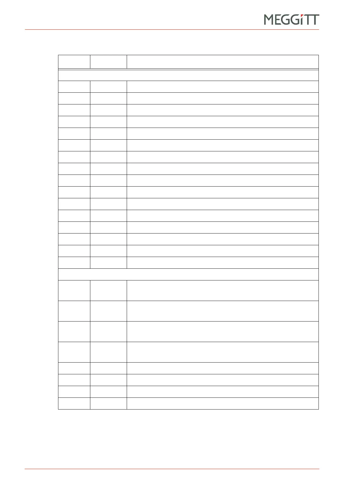
Definition of screw terminals on the IOC4T card
CONFIGURATION OF MPC4 / IOC4T CARDS
Connector J2
1 PS Tacho channel 1, power supply contact
2 HI Tacho channel 1, differential signal input (high)
3 LO Tacho channel 1, differential signal input (low)
4 SHIELD Tacho channel 1, shield contact
5 PS Tacho channel 2, power supply contact
6 HI Tacho channel 2, differential signal input (high)
7 LO Tacho channel 2, differential signal input (low)
8 SHIELD Tacho channel 2, shield contact
9 RL1 Contact of relay RL1
10 RL1 Contact of relay RL1
11 RL2 Contact of relay RL2
12 RL2 Contact of relay RL2
13 RL3 Contact of relay RL3
14 RL3 Contact of relay RL3
15 RL4 Contact of relay RL4
16 RL4 Contact of relay RL4
Connector J3
1DCOUT1
Processed DC output for measurement channel 1
(0 to 10 V or 4 to 20 mA)
2DCOUT2
Processed DC output for measurement channel 2
(0 to 10 V or 4 to 20 mA)
3DCOUT3
Processed DC output for measurement channel 3
(0 to 10 V or 4 to 20 mA)
4DCOUT4
Processed DC output for measurement channel 4
(0 to 10 V or 4 to 20 mA)
5 TM Trip Multiply input (control line)
6 DB Danger Bypass input (control line)
7 AR Alarm Reset input (control line)
8 RET Return line for TM, DB, AR and DC OUT n
Table 9-1: Definition of terminals for J1, J2 and J3 on the IOC4T card (continued)
Terminal Name Definition
 Loading...


