VM600 MPS hardware manual (standard version) MAMPS-HW/E 9 - 11
Edition 17 - February 2018
Connecting vibration and pressure sensors
CONFIGURATION OF MPC4 / IOC4T CARDS
9.2.2.2 Current-modulated signal
Applies to the following transducers or transducer and signal conditioner systems:
• CAxxx + IPC704 (2-wire, current modulation)
•CE1xx
•CE3xx
• CPxxx + IPC704 (2-wire, current modulation, Note: This setup is not recommended)
• CV210 + IVC632 (PS = −27.2 V, HI = COM)
•SE120
• TQ4xx + IQS45x (PS = −27.2 V, HI = COM).
Notes
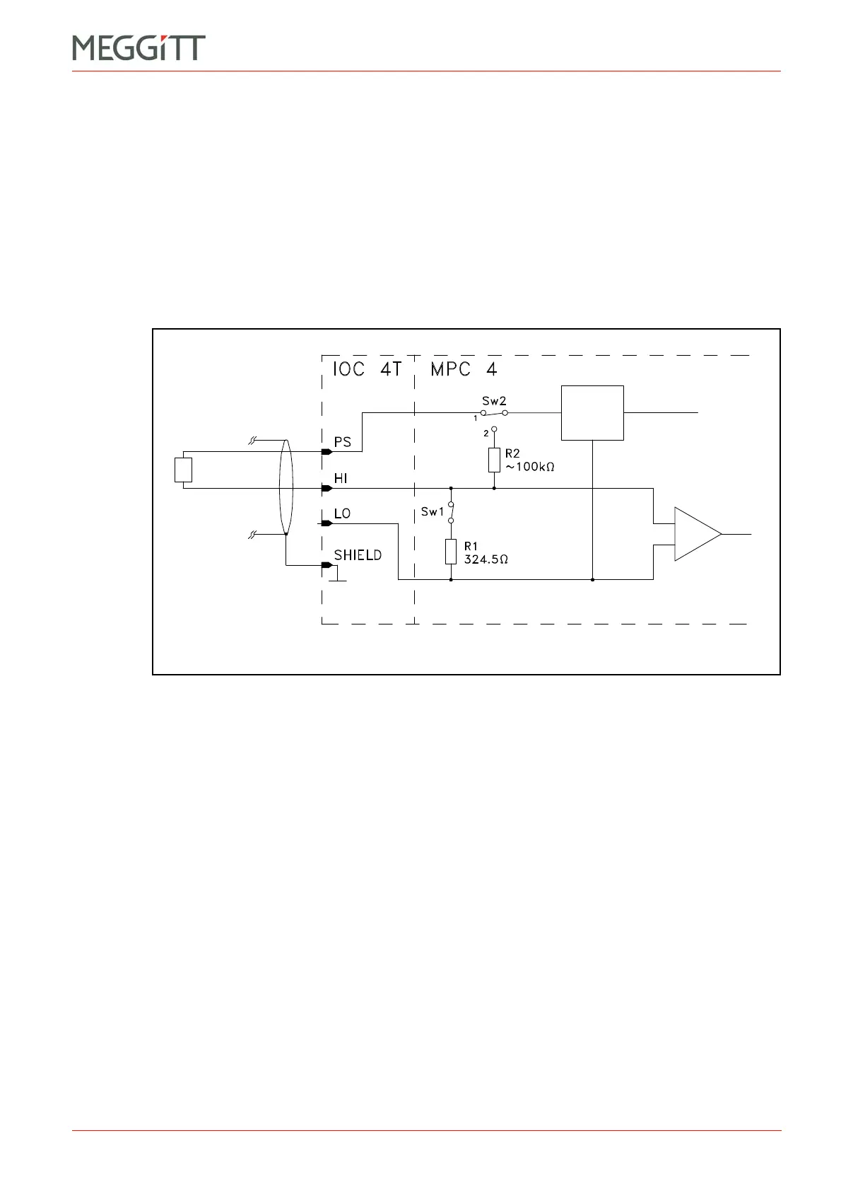
1- Switch Sw1 is closed to allow current-modulated signals to be processed.
For non-Vibro-Meter devices, the Signal Transmission Mode field has to be set to the
Current option.
2- Switch Sw2 is set to position 1 to connect the IOC4T card's sensor power supply to the
PS terminal.
For non-Vibro-Meter devices, the Sensor Power Supply field has to be set to the
appropriate voltage (+27 VDC, −27 VDC or +15 VDC).
Figure 9-5: Connection diagram
Sensor
power
supply
 Loading...


