VM600 MPS hardware manual (standard version) MAMPS-HW/E 9 - 17
Edition 17 - February 2018
Connecting vibration and pressure sensors
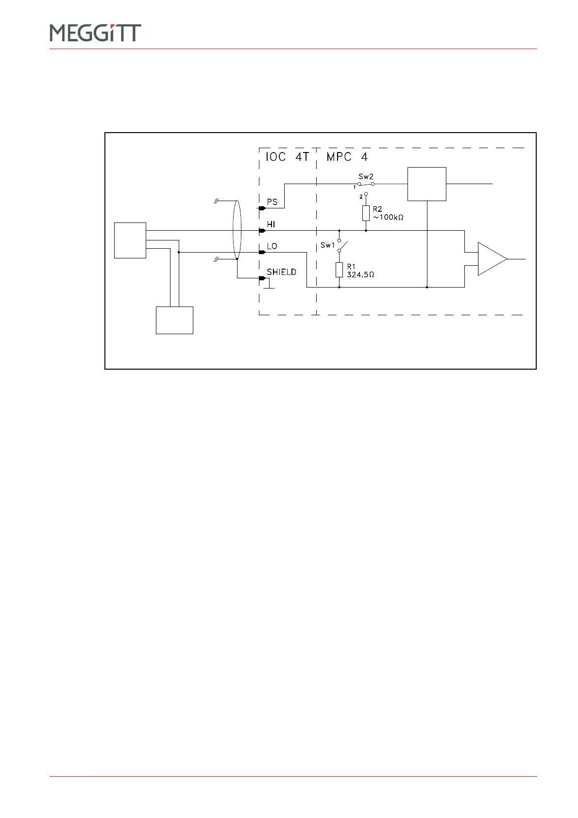
CONFIGURATION OF MPC4 / IOC4T CARDS
9.2.4.4 Voltage-modulated signal without galvanic separation unit
Applies to the following transducers or transducer and signal conditioner systems:
• LS12x + ILS73x (HI => MIN. GAP 0 to 10 V, LO => COM).
Notes
1- Switch Sw1 is open to allow voltage-modulated signals to be processed.
The Signal Transmission Mode field has to be set to the Voltage option.
2- Switch Sw2 is set to position 1. This connects the IOC4T card's sensor power supply to
the PS terminal, though in fact this terminal is not used.
The Sensor Power Supply field can be set to any powered option (+27 VDC, −27 VDC,
+15 VDC or +6.16 mA) but should preferably be set to +6.16 mA.
3- The operator must connect an external power supply to the transducer or transducer and
signal conditioner.
Figure 9-11: Connection diagram
Sensor
power
supply
External
power
supply
Signal
0V
Supply
 Loading...


