VM600 MPS hardware manual (standard version) MAMPS-HW/E 9 - 51
Edition 17 - February 2018
Assigning alarm signals to relays on the RLC16 card
CONFIGURATION OF MPC4 / IOC4T CARDS
For the sake of this example, we will assume that Raw Bus line 51 is chosen. Jumper J34
therefore has to be set on the RLC16 card.
Placing jumper J88 will ensure that Relay 7 is normally energised (see Table 9-7).
Jumper J338 now has to be set on the IOC4T card.
The user must then use the VM600 MPSx software to select Relay 7 from the 16 relays
available in the RLC/Raw bus node. Then, the Danger+ alarm for Output 1 of Channel 2 can
be assigned to this relay (see Figure 9-36).
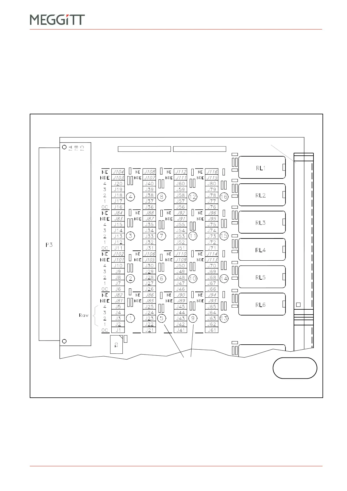
Figure 9-37: Position of jumpers on the RLC16 card related to the OC Bus and the Raw Bus
(Top of card)
(Bottom of card)
Relay numbers
Connector J1
RLC16
 Loading...


