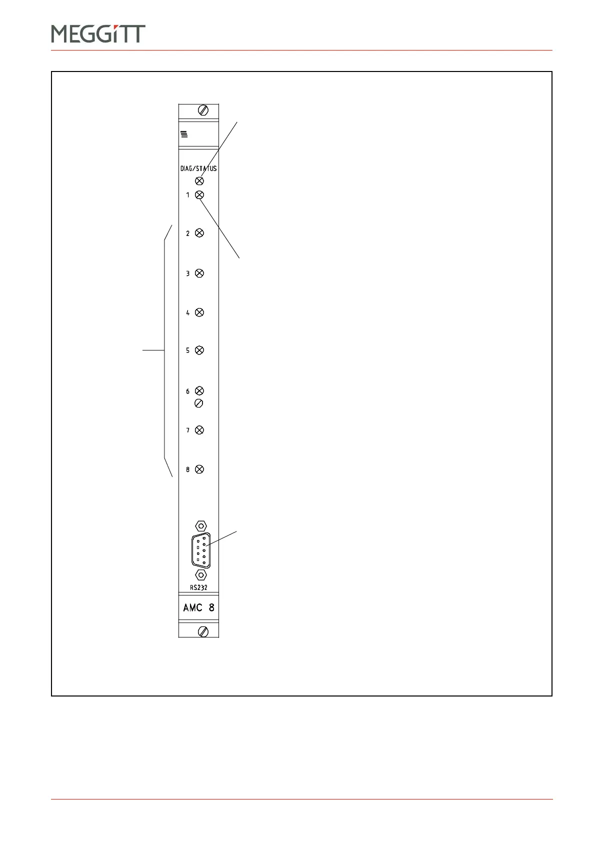
Figure 2-9: Elements on the AMC8
RS-232 connector
Can be used to configure an AMC8 card in a stand-alone rack
(without CPUM card) using the VM600 MPSx software.
Status indicator for the AMC8 / IOC8T card pair measurement channel 1.
The colours of the LED have the following significance:
* Off – Channel not configured or card not configured.
* Green (continuous) – Signal input to the channel is valid and there are
no active alarms.
* Green blinking – Signal input to the channel is not valid.
* Green blinking slowly – Channel inhibit function active.
* Yellow (continuous) – There is an active single-channel processing
Alert level alarm ((A) or (A+)).
* Red (continuous) – There is an active single-channel processing
Danger level alarm ((D) or (D+)).
Status indicator for
the AMC8 / IOC8T
card pair
measurement
channels 2 to 8.
Operation as per
measurement
channel 1.
DIAG/STATUS indicator for the AMC8 / IOC8T card pair.
The colours of the LED have the following significance:
* Green (continuous) – Normal operation (configuration valid with no active
alarms and no errors).
* Green blinking – Card is configured but still in the stabilisation phase.
* Yellow (continuous) – There is an active multi-channel processing
Alert level alarm ((A) or (A+)).
* Yellow blinking – Configuration error and/or signal processing error.
* Red (continuous) – There is an active multi-channel processing
Danger level alarm ((D) or (D+)).
* Red blinking – Hardware error or card not yet configured.
Notes:
See also Table 5-1 and Table 5-2 for further information
on the behaviour of AMC8 card LEDs.

 Loading...


