VM600 MPS hardware manual (standard version) MAMPS-HW/E 2 - 41
Edition 17 - February 2018
RPS6U rack power supply (ABE04x only)
OVERVIEW OF VM600 MPS HARDWARE
Notes
1- General Remarks:
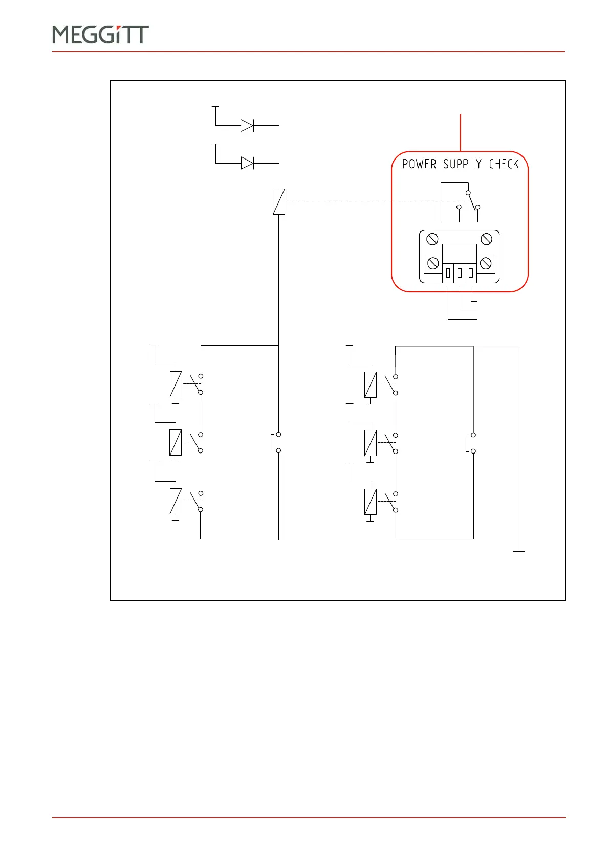
• Jumpers J16 and J17 have to be set according to which RPS6U rack power supplies
are used (PS1, PS2 or both).
• Relays RL1 to RL6 are closed when the corresponding supply voltage (+5 V, 12 V
or +12 V) is present and correct.
• When no problem is detected, relay R7 is energised and contact is made between
the power supply check relay’s COM and NO contacts.
• If a problem is detected, relay R7 is de-energised and contact is made between the
power supply check relay’s COM and NC contacts.
2- When only the first RPS6U (PS1) is installed (slots 18 to 20):
• Jumper J16 must be left open
• Jumper J17 must be closed.
Figure 2-29: Operation of the power supply check relay for the RPS6U power supplies
installed in a VM600 rack (ABE04x)
Common (COM)
Normally open (NO)
Normally closed (NC)
On rear panel
+5 V
PWS1
+5 V
PWS2
+5 V
PWS2
+12 V
PWS2
–12 V
PWS2
+5 V
PWS1
+12 V
PWS1
–12 V
PWS1
RL7
RL1
RL2
RL3
RL4
RL5
RL6
J17
J16
0V
PS2 (RPS6U) PS1 (RPS6U)
 Loading...


