3 - 8 VM600 MPS hardware manual (standard version) MAMPS-HW/E
Edition 17 - February 2018
VM600 6U 19" rack backplane (ABE04x)
GENERAL SYSTEM DESCRIPTION
14
3
2 5 6 7 8 9 10 11 12 13 140
15
18
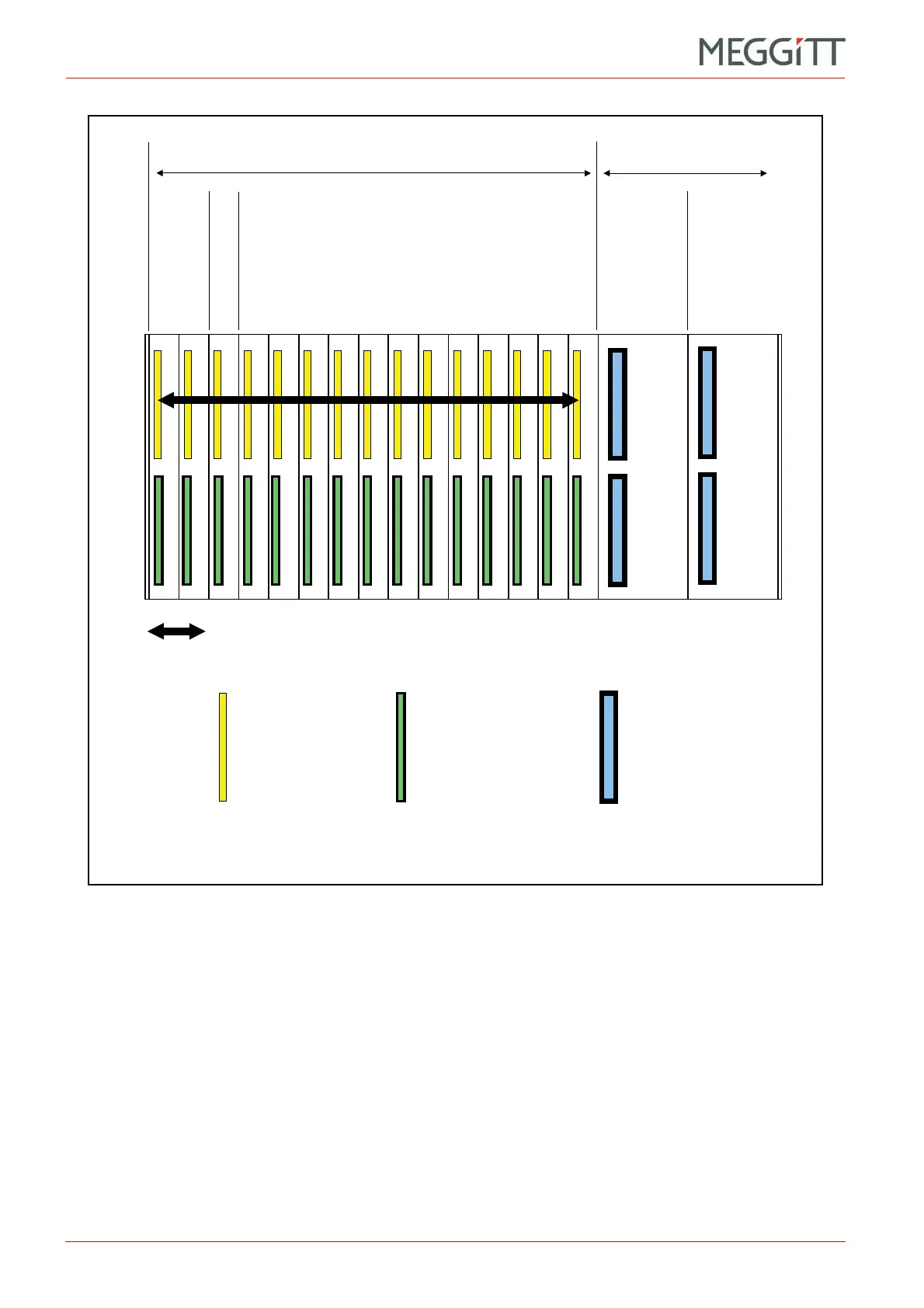
Figure 3-4: Diagram of VM600 rack (ABE04x) backplane
showing the arrangement of the connectors
15 module slots (VME) 2 power supply slots
These 12 slots accept MPC4 or AMC8 cards RPS6U
rack power
supply
RPS6U
rack power
supply
VME P1 bus (all VME 16 signals)
P1 connector wired
according to
VME 16
specification
P2 connector used for
rear-to-front signal
connection and control
of the IOC card by the
MPC4 or AMC8 card
Special high-current
connector
CPUM
card
Reserved
Slot
 Loading...


