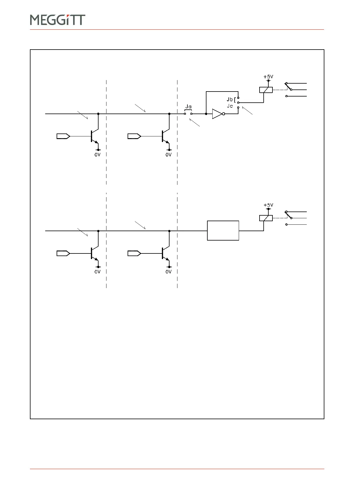
Figure 3-7: Using of one of the 16 OC Bus lines to switch a relay on a RLC16 or IRC4 cards
IOC in slot n IOC in slot n+1
RLC16 in slot m
n = {3, 5, 7, 9, 11 or 13}
m = {1, 2, 15, 16, 17 or 18} for the OC Bus
Open collector
driver
One of the 16
lines on OC Bus x
Jumpers to select
OC Bus line
Jumpers to select
relay NE/NDE
(see note 2)
RELAY #A
(see note 3)
Control signal
(see note 1)
Control signal
(see note 1)
Notes
1. Specific alarms (A+, D and so on) are attributed to the OC Bus lines using the VM600 MPSx software.
See Table 9-4 for information on the normal state of the control signal.
2. For a normally energised (NE) relay, select an inverted relay control line by placing jumper Jc.
For a normally de-energised (NDE) relay, select jumper Jb.
Either Jb or Jc must be selected (that is, it is not possible to select both or to select neither).
3. Relay #A represents one of the 16 relays (RL1 to RL16) on the RLC16 card.
4. Relay #B represents one of the 8 relays (4 DPDT or 8 SPDT) on the IRC4 card.
IRC4 in slot m
m = {1, 2 or 15} for the OC Bus
RELAY #B
(see note 4)
Logic
m = {1 to 18} for the Raw Bus
m = {1 to 15} for the Raw Bus
Open collector
driver
One of the 16
lines on OC Bus x
 Loading...


