Operating Instructions - CPC6050 133
Modular Pressure Controller
CPC6050
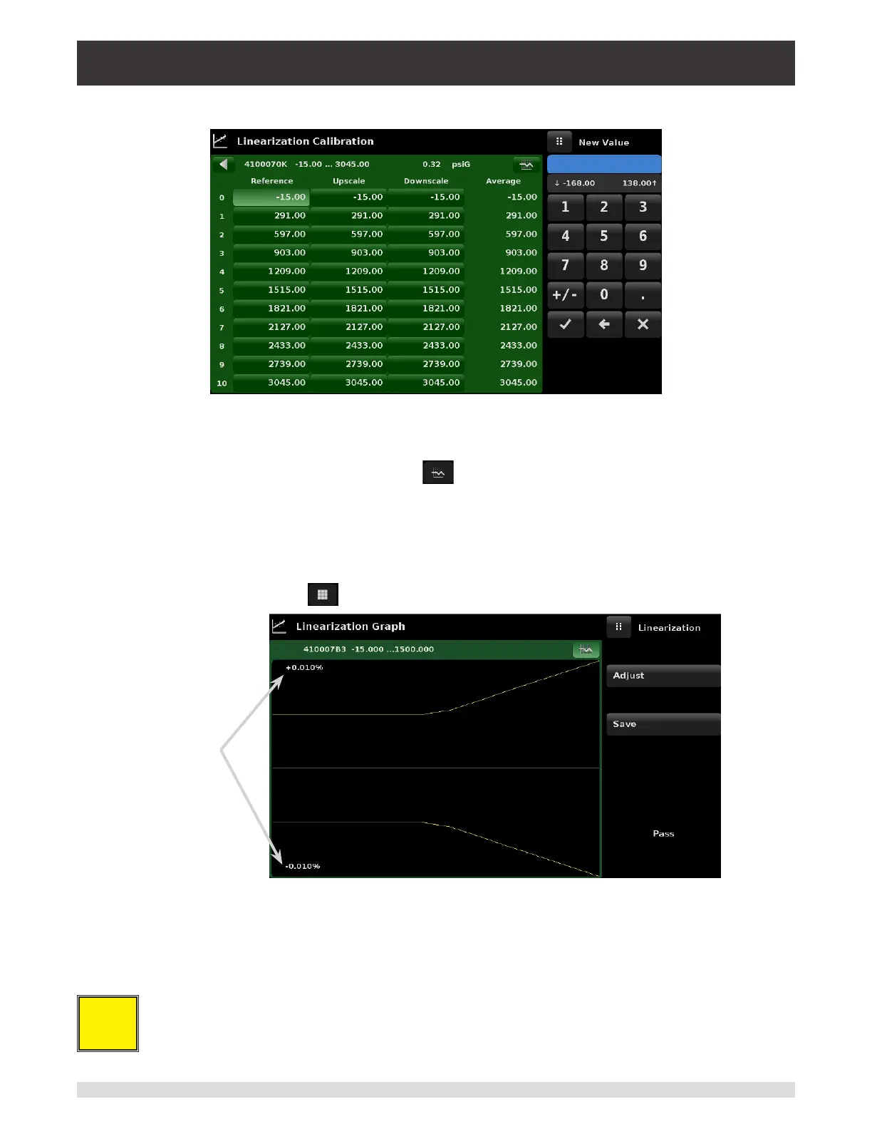
and downscale values.
Figure 10.9-B - Linearization Values
Figure 10.9-B shows some typical values that might be seen in a linearization calibration. In the bottom
right hand corner of this screen is the Graph Icon [ ] that, when pressed, reveals a Linearization
Error Graph (gure 10.9-C) that gives a visual representation of the errors associated with the values
entered in the Linearization screen.
This Linearization error graph shows a scaling that corresponds to the maximum error calculated from
the data entered in the Linearization Matrix. It is a good indication of the overall error of the transducer,
and will quickly reveal any gross data entry errors that have been made. To revert back to the Lineariza-
tion Matrix press the Matrix Icon [ ].
Relative
Scale
Figure 10.9-C - Linearization Error Graph
When satised that all values have been entered correctly, press the adjust button and then the save but-
ton to save the new calibration data in the transducer memory.
i
Note: After calibration is complete, return to the Calibration Data Application (Section 10.6)
to record the certicate number, calibration interval and the date of calibration. Restoration to
factory calibration can also be completed in this application.