Operating Instructions - CPC6050 69
Modular Pressure Controller
CPC6050
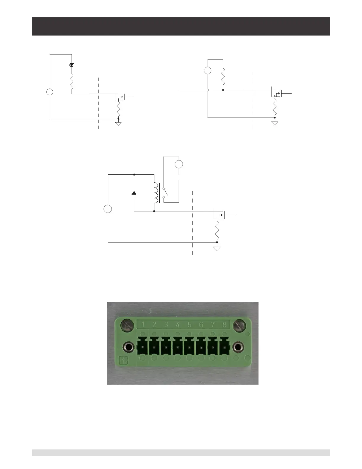
0.75 Ω
Internal Control Signal
Rear Panel
+
-
Current
Limiting
Resistor
Exernal
5.0 VDC
Supply
Figure 7.1.1.2-B Digital Output with LED
0.75 Ω
Internal Control Signal
Rear Panel
+
-
10 KΩ
Exernal
Logic
Supply
Voltage
To Logic Input
Figure 7.1.1.2-C Digital Output with Logic Device
0.75 Ω
Internal Control Signal
Rear Panel
+
-
Exernal
Voltage
Supply
Load
Relay
+
-
Load
Voltage
Supply
Flyback
Diode
Figure 7.1.1.2-D Digital Output with Relay
Connector Pin Out designation corresponds to numbers on the connector:
1 – Ground
2 – Input #1
3 – Input #2
4 – Input #3
5 – Ground
6 – Output #1
7 – Output #2
8 – Output #3