– 5.4 –
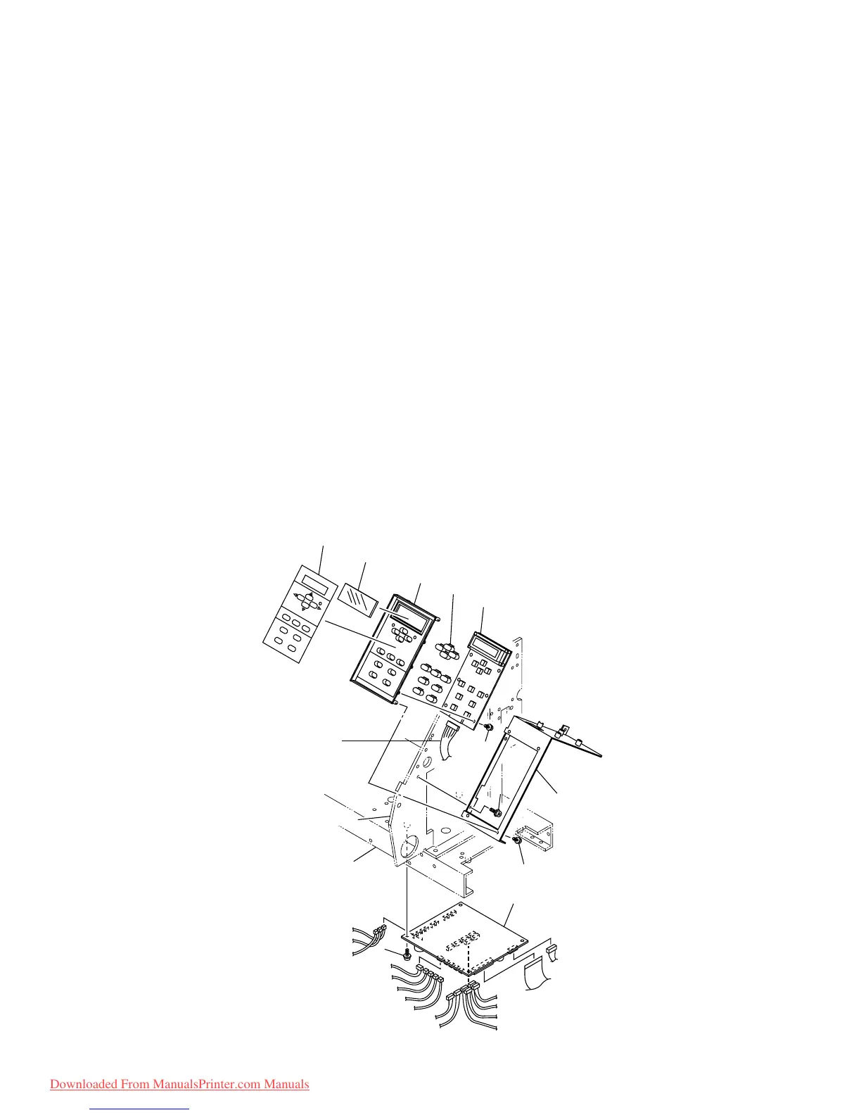
5-1-2. Keyboard assy. and IO PCB assy.
[Tools to be used]
• Phillips screwdriver (No. 2 for M3 to M5)
[Disassembling procedure]
<Keyboard PCB>
1) Remove the right cover.
2) Remove the keyboard cable assy.
3) Remove the screw (P4 x 6SMW), then remove the keyboard base from right side plate.
4) Remove the screw (TP3 x 8), then remove the keyboard PCB assy. from keyboard base.
5) Remove the keyboard PCB from keyboard panel.
<IO PCB>
1) Remove the screw (B4 x 10Bk), then remove the IO cover.
2) Remove the cables of the sensor and motor connected to the IO PCB assembly.
3) Remove the screw (P3 x 8SMW), then remove the IO PCB assy. from under flame.
[Assembling procedure]
• Assembly is reverse of disassembly.
to Fan motor 3 assy.
to Wiper sensor assy.
to Under point sensor assy.
to Paper sensor assy.
to Clamp sensor assy.
to Origin sensor assy.
to Pump motor 1 assy.
to Pump motor 2 assy.
to Pump motor 3 assy.
to Pump motor 4 assy.
to Station motor assy.
to IO cable assy.
to Wiper motor assy.
to Take-up device
junction cable assy.
to Fan motor 2 assy.
to Fan motor 1 assy.
to Main PCB
assy. CN5
KB seat
LCD cover
KB panel
Key top
KB PCB assy.
KB cable assy.
KB base
TP3 x8
IO PCB assy.
Right side plate
Under flame
TP3 x8
Downloaded From ManualsPrinter.com Manuals
 Loading...


