– 5.5 –
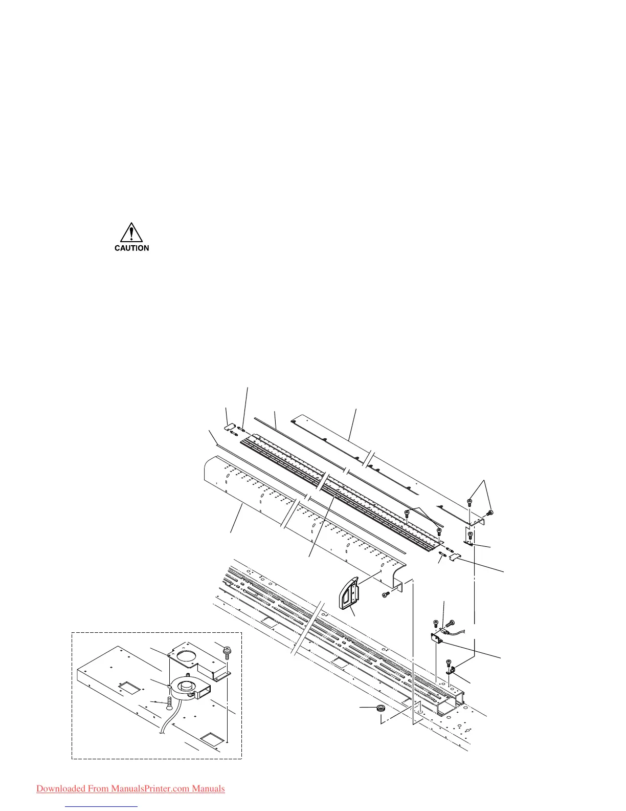
5-1-3. Platen cover F/R, Fan motor assy., and Paper sensor R assy.
[Tools to be used]
• Phillips screwdriver (No. 2 for M3 to M5)
[Disassembling procedure]
1) Remove the screw (B3 x 6Ni), then remove the platen cover F. (B3 x 6Ni)
2) Remove the screw (B3 x 6SMW), then remove the fan motor BKT from under flame.
3) Remove the screw (F3 x 8Bk), then remove the fan motor assy. from fan motor BKT.
• Note that cables with different lengths are used for the three fan motors (four fan
motors with the JV4-180) depending on the mounting position.
4) Remove the screw (B3 x 6Ni), then remove the platen cover R.
5) Remove the screw (P3 x 6Ni), then remove the paper sensor R BKT from under flame.
6) Remove the screw (B3 x 10Bk), then remove the paper sensor R assy. from the paper
sensor R BKT
[Assembling procedure]
• Assembly is reverse of disassembly.
to IO PCB assy.
CN4
B3 x6Ni
B3 x6Ni
B3 x6Ni
B3 x10Bk
B3 x6Ni
B3 x6Ni
Media guide shaft
Media guide
Media guide shaft
Media guide
Paper sensor
assy.
Platen rubber
Platen cover R
Platen cover F
Platen F
Paper sensor
R BKT
P-cover BKT
P cover BKT 2
Grommet
Support assy
P-cover F rubber
P3 x6SMW
F3 x8Bk
Fan motor
BKT
Fan motor assy.
Downloaded From ManualsPrinter.com Manuals
 Loading...


