– 5.9 –
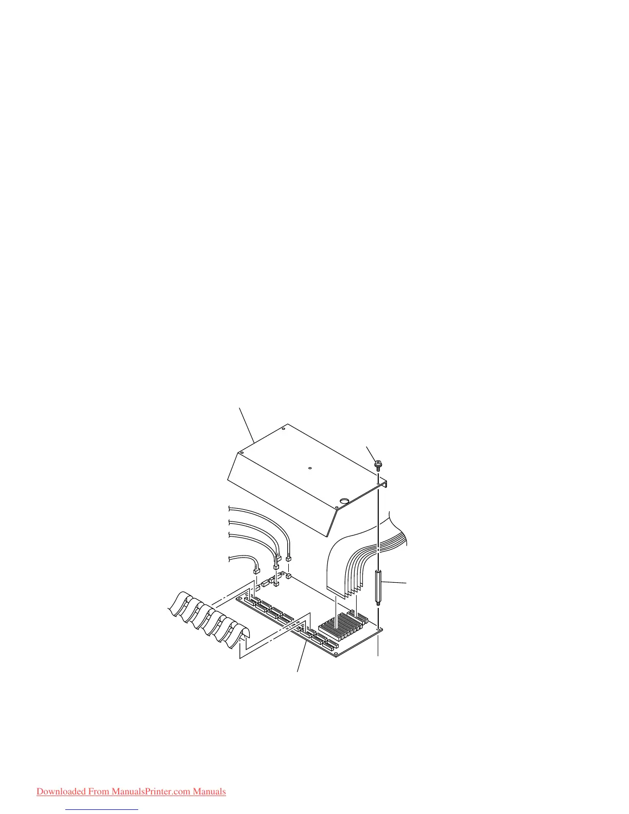
5-1-7. Head cover, Slider PCB and Linear encoder PCB assy. / scale
[Tools to be used]
• Phillips screwdriver (No.2 for M3 to M5)
• Phillips screwdriver (No.1 for M2)
• Box wrench (opposite side distance: 5.5 mm)
• Phillips screwdriver (for removing SP)
[Disassembling procedure]
1) Turn ON the power of the device and then move the slider to the center of the platen using
the JOG key.
2) Turn OFF the power supply switch, remove the front cover and the Y cover.
3) Remove the screw (B3 x 6Bk), then remove the head cover.
4) Remove the screw (P3 x 6SMW), then remove the FPC cover.
5) Remove all of the harnesses on the slider PCB.
6) Remove all of the spacers (SQ-25) that hold the slider PCB.
7) Replace the slider PCB.
[Assembling procedure]
• Assembly is reverse of disassembly.
to HDC-4Head PCB assy.
CN2~6
to HDC-2Head PCB assy.
CN3~4
to Cutter actuator assy.
to Linear encoder assy.
to Cap sensor assy.
to Paper width sensor assy.
P3 x6SMW
FPC cover
Slider PCB assy.
Spacer
Downloaded From ManualsPrinter.com Manuals
 Loading...


