– 2.11 –
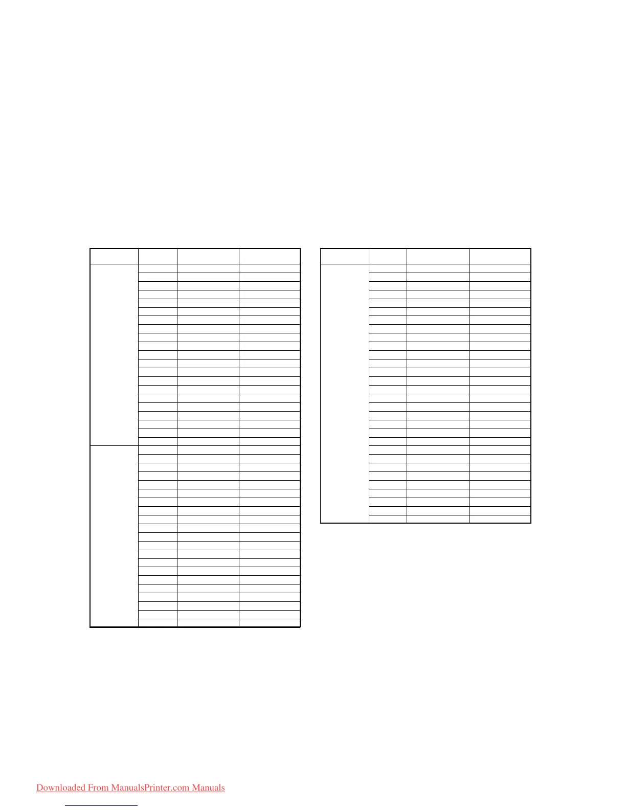
Connector Pin No. Signal Name Remarks
1 SIO02A
2 SIO01A
3 SCK02A
4 SCK01A
5 H1anodeA
6 H1CHA
7 GND
8 H1LATA
9 GND
10 H1NCHGA
11 GND
12 +5V
13 H1-TH
14 GND
15 GND
16 H1COMA
17 GND
18 H1COMA
19 GND
20 H1COMA
21 GND
1 SI001B
2 SI002B
3 SCK01B
4 SCK02B
5 H1anodeA
6 GND
7 H1CHB
8 GND
9 H1LATB
10 GND
11 H1NCHGB
12 +5V
13 GND
14 GND
15 H1COMB
16 GND
17 H1COMB
18 GND
19 H1COMB
20 GND
21 +42V
CN1
~
CN8
CN9
~
CN16
Connector Pin No. Signal Name Remarks
1 GND
2 SOLCOM
3PAPER-CUT
4 GND
5 MARK2 Reserved (Tx)
6 MARK1 Reserved (Tx)
7T-LEDON
8 GND
9 LENCB1
10 LENCA1
11 KP-SEN
12 P-WID-SEN
13 GND
14 SLOP
15 ADI
16 GND
17 A4INH3
18 A4INH2
19 A4INH1
20 A4C
21 A4B
22 A4A
23 ASCK
24 ACS
25 GND
26 GND
27 +5V
28 +5V
29 +5V
30 GND
CN17 /
CN18
2-1-9. Slider PCB
The slider PCB is located on the inner side of the head cover. It relays the head control signal
and head driving signal from the HDC PCB to the print heads. It contains the sensor circuit
which detects the signal from the thermistor on each head and the signal from the paper-
width sensor.
The slider PCB is connected to the HDC PCB with 7 main FPC cables and connected to the
heads with 12 head FPC cables. In addition, the slider PCB is connected respectively to the
linear encoder that detects the ink discharging position with the linear scale, to the paper
width sensor PCB and to the cutter solenoid.
Slider PCB Connector signals
Downloaded From ManualsPrinter.com Manuals
 Loading...


