124
1
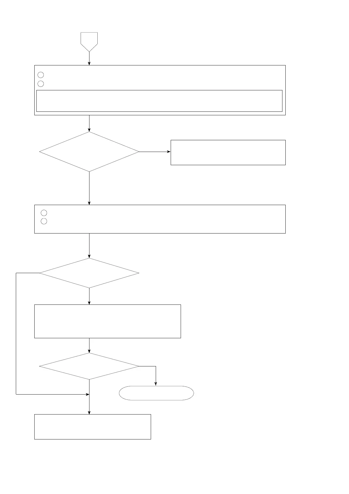
Remove the connecting cable for strain gage applied transducer from the terminal board.
2
Measure the voltage between the A−C terminals on the terminal board.
Set the connecting range to DC・V for the measuring instrument such as tester and so
on.
1
Short the B, D and COM.1 on the terminal board.
2
Set the load display section to be the monitoring condition for strain gage
applied transducer according to the paragraph 7−15.
The display stabilizes
with the optional
value.
The voltage between
A−C is the same as the setting
with F−12 and stable
as well.
8
Inform Minebea about the contents of
failure and situation at site in details.
Inform Minebea about the contents of
failure and situation at site in details.
Check the various kinds of connecting conditions
according to the procedures in the chapter 4.
Especially, check that there may have effects from
the noise source such as an inverter or like that.
Start measurement.
Same condition
YES
NO
NO
NO
YES
YES