123
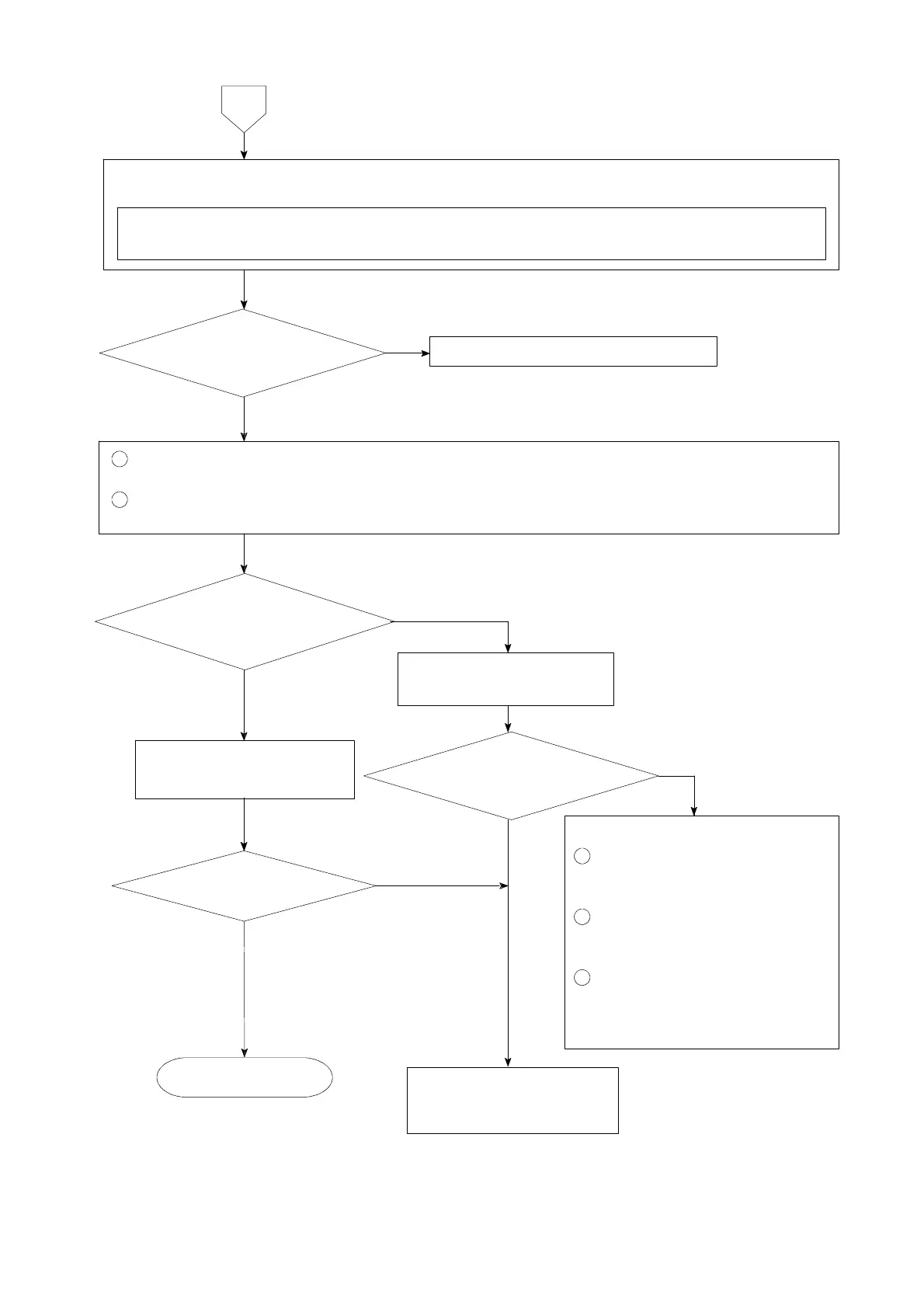
Set the connecting range to DC・V for the measuring instrument such as tester and so on.
① Remove the connecting cable for strain gage applied transducer from the terminal board.
② Measure the voltage between the A−C terminals on the terminal board.
1
Connect the connecting cable for strain gage applied transducer to the terminal board again.
(Refer to the chapter 4.)
2
Set the load display section to be the monitoring condition for strain gage applied transducer
according to the paragraph 7−15.
Monitoring display
exceeds the range from −0.3 mV/V
to 2.4 mV/V.
The voltage between
A−C is the same as the setting
with F−12.
7
Inform Minebea about the
contents of failure and
situation at site in details.
Contact with Minebea.
Short between B−Don
the terminal board.
Start measurement.
Same condition
Make re−calibration
according to the procedures
of chapter 5.
YES
Following causes can be considered
1
The input of strain gage applied
transducer exceeds the range
from −0.3 mV/V to 2.4 mV/V.
2
The strain gage applied
transducer has broken due to
overload and so on.
3
The strain gage applied
transducer connected has broken
or signal route (signal wire) has
cut off.
YES
NO
YES
NO
NO
NO
YES
Monitoring display
exceeds the range from −0.3 mV/V
to 2.4 mV/V.