18. Interface specifications
MiR600 User Guide (en) 08/2021 - v.1.0 ©Copyright 2021: Mobile Industrial Robots A/S. 228
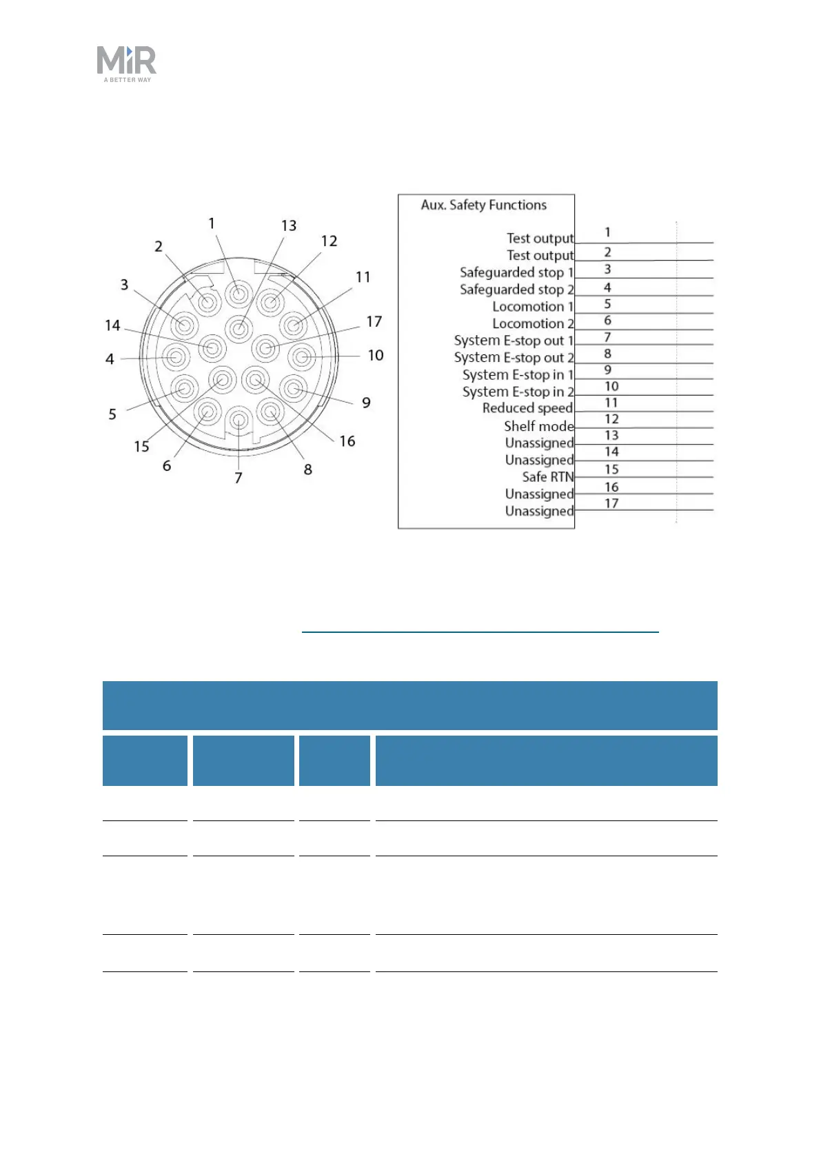
Auxiliary safety functions
Figure 18.7. Pin numbers: female connector viewed from the front (left) and wiring diagram (right).
The Auxiliary safety functions interface is designed to support safety functions that can
trigger a Protective stop—see Safety-related functions and interfaces on page96.
Table 18.5 contains the description of the pins of the Auxiliary safety functions interface.
Pin
number
Signal
name
Type Description
1 Test output Output 24V output.
2 Test output Output 24V output.
3 Safeguarded
stop 1
Input When inactive, the robot enters Protective stop.
If pins are unequally set for a period greater
than three seconds, the robot must be restarted.
4 Safeguarded Input When inactive, the robot enters Protective stop.
Table 18.5.
Description of the pins in the Auxiliary safety functions interface