98
F
ITTING THE COMMUNICATION SERVER
CHAPTER 4 INSTALLATION
7. Secure the cage nuts in the appropriate positions in the rack’s fastening rails (see Placing two
communication servers above each other inside a 19” rack).
8. Secure the communication server to the rack’s fastening rails using the M6 screws, the plastic
washers and the cage nuts.
9. Fasten the snap-on tag to the front panel.
10. Reconnect the communication server to the power supply.
Installing the cable cover
Materials required:
• Cable cover set
• Screwdriver
To install the cable cover proceed as follows:
1.
Pull off the screw covers on the left and right of the front panel.
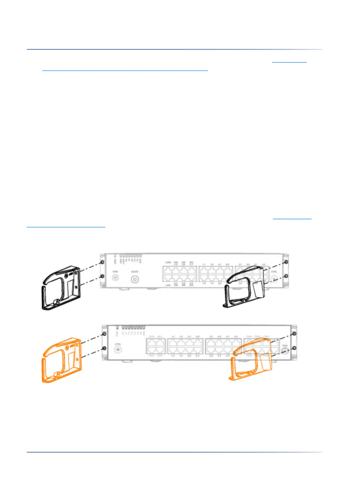
2. Use the M4 screws of the cable cover set to secure the brackets for the cable cover to the commu-
nication server.
NOTE: The two brackets are not identical. Compare the cable brackets with the ones in Installing the
brackets for the cable cover.
3. Fit the cable cover over the brackets from above until they are felt to engage.
Figure 4.7: Installing the brackets for the cable cover
Figure 4.8: Installing the brackets for the cable cover
TIP: To remove the cable cover reach into the side openings of the cover, gently press the two (engaged)
lugs outwards and remove the cover.