155
I
NSTALLING, POWERING, CONNECTING AND REGISTERING TERMINALS
CHAPTER 4 INSTALLATION
• Minimum distance between charging bays with cordless phones on-hook for faultfree operation: 0.2
m.
Ambient conditions
• When installing: Ensure convection (space for ventilation).
• Avoid excessive dust.
• Avoid exposure to chemicals.
• Avoid direct sunlight.
• See also technical data in Mitel DECT radio units
.
NOTE: If these requirements cannot be met (e.g.outdoor installation), use the appropriate protec-
tive housing.
Installing the radio units
Do not remove the cover of the radio unit. (Warranty protection will lapse if the cover is removed)
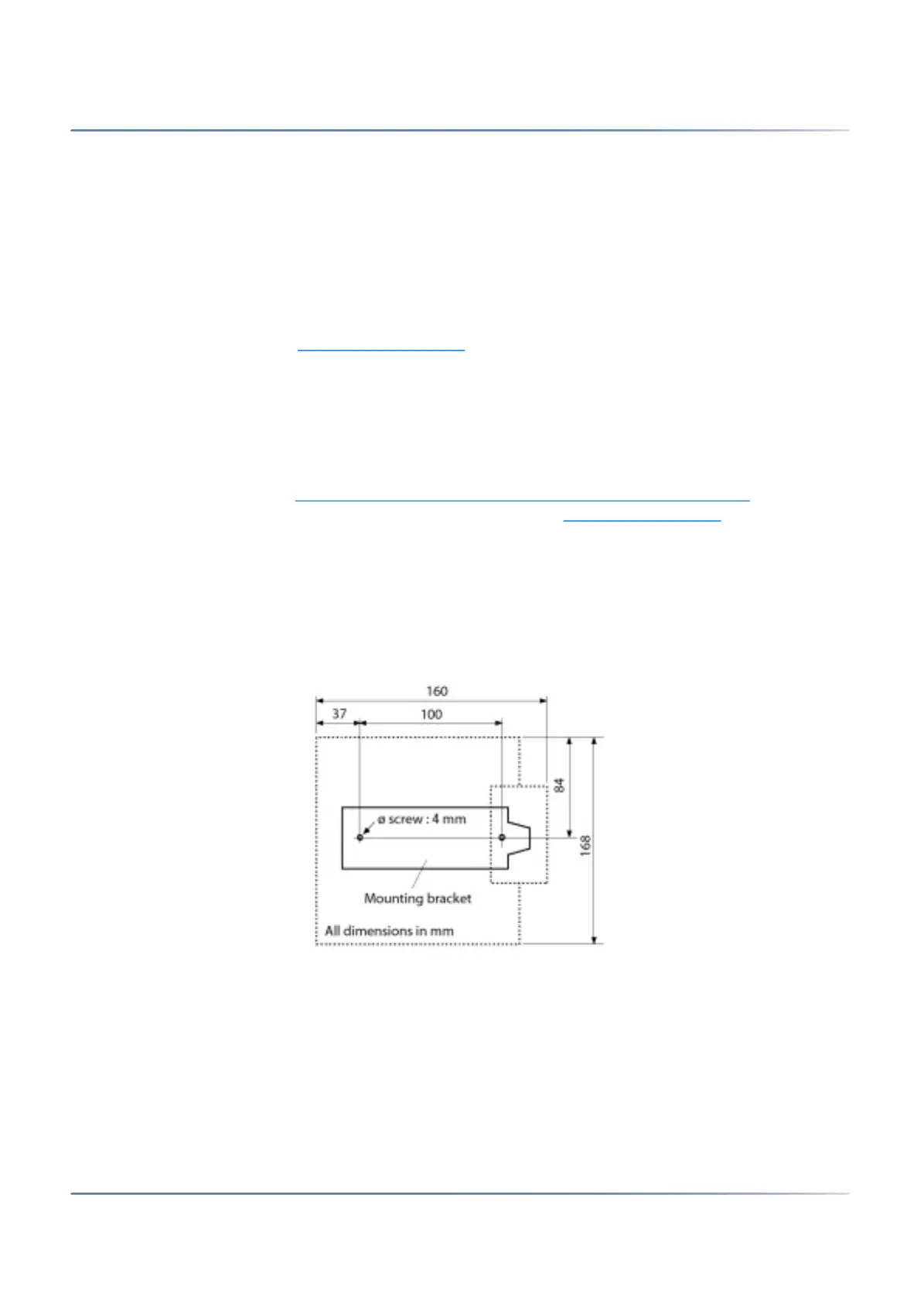
Fit the mounting bracket (see Dimensional drawing for wall-mounting the mounting bracket
dimensional
drawing for wall mounting). Observe the minimum distances (see Installation distances
).
Position the DSI socket(s) near the radio unit.
Each radio unit requires one DSI bus (two optional on the SB-8): Do not connect any other terminals.
The radio units can be powered from the communication server up to the maximum line length of 1200 m
specified for operation (wire diameter 0.5 mm). The plug-in power supply unit for is the same as the one
for the Office 135 charging bay.
Figure 4.55: Dimensional drawing for wall-mounting the mounting bracket