119
C
ABLING INTERFACES
CHAPTER 4 INSTALLATION
See also:
System Manual “PISN / QSIG Networking”
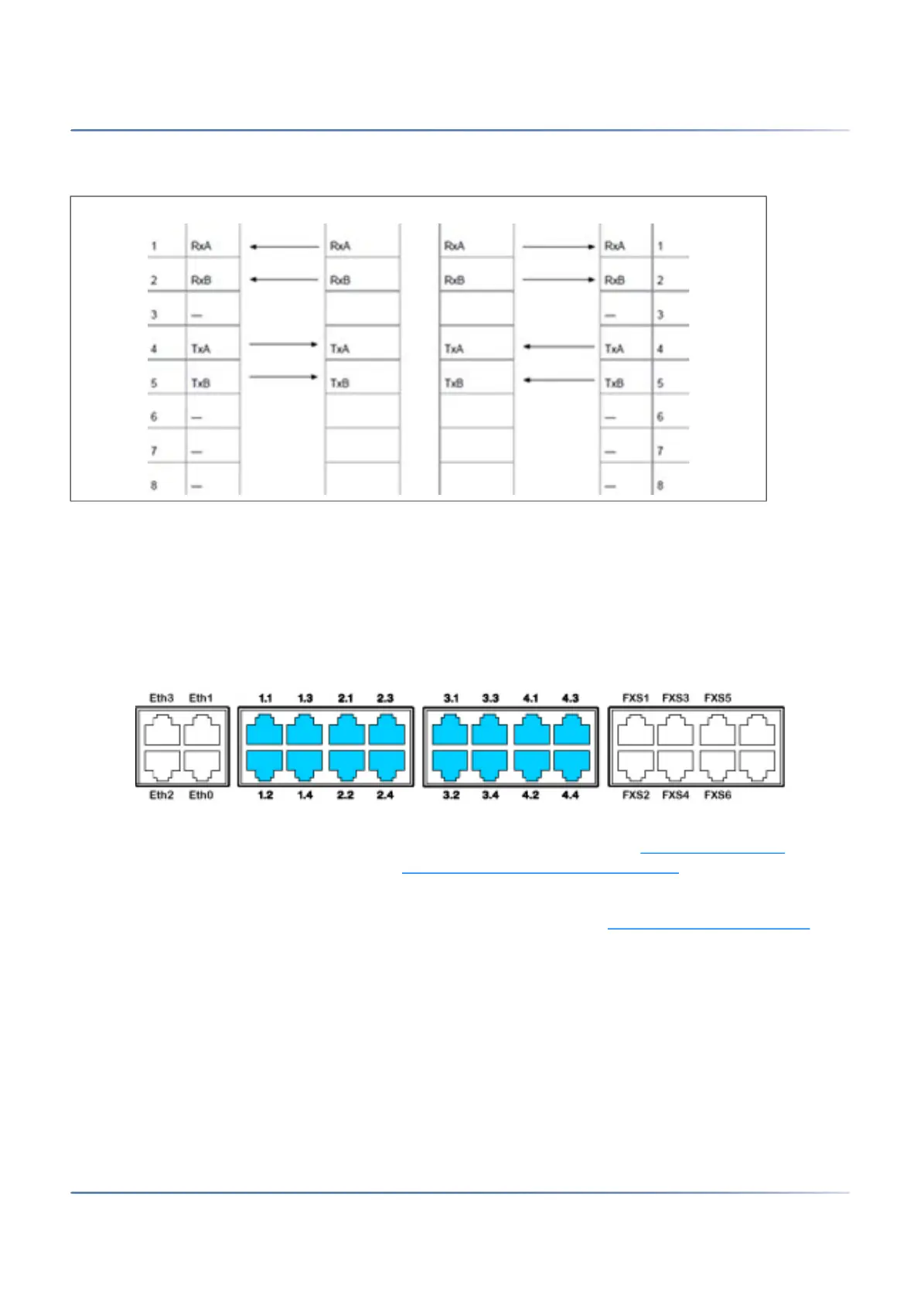
FXO network interfaces
With the appropriate interface cards and wiring adapters, FXO network interfaces can be made available
at RJ45 sockets 1.x...4.x. The possible RJ45 sockets are highlighted in colour in the figure below.
Figure 4.28: Connection possibilities for FXO network interfaces
On cards with 16 interfaces RJ45 sockets 9 to 16 are multiply assigned. The signals can be split again to
individual RJ45 sockets using patch cables and the fan-out panel FOP (see Fan-out panel FOP
) or with
8-fold assigned connecting cables (see e.g. Prefabricated system cable 4 x RJ45
).
Multiply assigned RJ45 sockets are colour-coded in blue.
One call charge module can be fitted to each FXO card if required (see Fitting call charge modules
).
In a direct connection the RJ45 connector is connected directly to the trunk cable using a crimp clip.
With an indirection connection you need to observe the cable requirements.
NOTE: Circuit type as per EN/IEC 60950: TNV-3
NOTE:
• Inadmissibly high temperatures can occur on the FXO card when connecting to local exchanges
generating a very high loop current (up to 90mA). If so, the PCB temperature monitoring deacti-
vates the FXO ports in groups of 4 ports. If the temperature then drops, the FXO ports are automat-
ically reactivated group by group. This behaviour can occur particularly when the ambient
Table 4.15:Cabling for primary rate interface, PRI, networked with leased-line or dial-up connection (Continued)
(Sheet 2 of 2)